Davectr Posted September 21, 2016 Share Posted September 21, 2016 Fantastic write up Hodaka, have really enjoyed catching up with what you have been doing. Some impressive work done there mate. Will keep a close eye on your progress 👠Quote Link to comment Share on other sites More sharing options...
Hodaka Posted September 21, 2016 Author Share Posted September 21, 2016 Woah, sudden activity on my dormant thread! Thanks for the comments! Got loads of things I'm working on and will update again once I actually finish! The headlight has been opened up again as I decided I wasn't happy with the projectors themselves, so now working on retrofitting some cheap but decent HID projectors. Starting to wonder if I'll ever see these on my car though as I just keep changing my mind about everything! Got the same spoiler delivered today. Did you attach it yourself, just wondering if its a one man job. I got my garage to do it so I can't help you there I'm afraid! The spoiler looks great though, you'll be very pleased no doubt Quote Link to comment Share on other sites More sharing options...
Hodaka Posted October 10, 2016 Author Share Posted October 10, 2016 (edited) Evening! It's been a while since my last proper update! I've got lots of things bubbling away, but I've "finished" my strut bar lights, so I thought I'd post about those. I have a habit of droning on, so I'll do my very best to be as concise as possible! In short, the goal was to paint my strut bar cover, as well as putting some lights under the zed itself. First I removed the strut bar cover: Here's what it looks like underneath. The Z emblem is held on by 5 rivets (?): So I ground the plastic rivets off: With a bit of encouragement, i.e. poking it with a screwdriver, the emblem came off: I then sanded away the posts: I then traced the Z emblem: And cut out a piece of acrylic: After a bit more cutting & sanding: My plan was to use the 5 holes + 1 that I was going to drill. Here's the layout I came up with: So I cut/sanded/ground the plastic so that the LEDs would sit flush: I also stuck some masking tape on the acrylic Z to try and diffuse the light: I decided to stick some reflective tape on the underside of the Z emblem: After I'd stuck it on: I put it all together and tested it out: I was happy with the progress, but not with the light distribution. A lot of Goolging later I came across someone saying that you can cut off the domed part of the LED to increase the angle of light emitted. Here's a pic, along with another shape I tried: To me, the flat LED seemed to distribute the light more, so I went with that. Another thing I read is that you can drill an indentation in the flat top to further increase the angle. So I thought I may as well And to make things more hasslesome, I sanded the LEDs... Again, to try and increase the angle of light: I then wired up the LEDs in triplets along with resistors. These were then wired in parallel: I also bought some actual diffusal film so stuck that on with super glue. I didn't think it would help much as the LEDs would be so close to the film, but again, I thought it's worth a shot! In retrospect though, I would have preferred to have scuffed up the acrylic instead as I couldn't get the diffusal film to stick perfectly on the acrylic: Edited October 10, 2016 by Hodaka Quote Link to comment Share on other sites More sharing options...
Hodaka Posted October 10, 2016 Author Share Posted October 10, 2016 (edited) As for the strut cover, I had to cut out more plastic to make way for the LEDs: Here's a pic with the LEDs in place: And the back: I then painted the strut bar cover: And here's the end result: Looked good from above, but I couldn't think of a good mounting method and I really wasn't happy with how messy the circuitry was. I therefore went back to the drawing board. After a bit of thinking, I remembered perfboards/protoboards. I thought it would be a great way of providing an actual rigid structure for the circuit: I cut it into strips, stuck on some reflective tape and poked holes into it: And soldered the components: Here's a comparison of version 2 (top) and version 3 (bottom): I was much happier with this, so I mounted it to the strut bar cover. I used epoxy to stick some standoffs to the cover, then used screws + washers to hold the circuit in place. In an attempt to prevent electrical shorts, I covered the circuit board and undersides of washers with electrical tape: Much better I was happy enough with the above that I installed it back in the car. In terms of wiring it up, I tapped into the boot light. A very big thing to note if you ever do something similar, is that the positive side of the boot light is always live! It's actually the ground that gets broken (?) via a switch! I had to redo the wiring as I thought it's the live side that gets switched... I did do some searching after I found out, and noticed a few other members on here have faced the same issue. PITA! Anyhow, I don't have a good pic of it installed so I won't bother. A few weeks later my wife messaged me to say her brake light was out. I told her to meet me at Halfords after work and I replaced it for her. I also polished her exhaust (no, don't even go there!) as we both had some time. During this I had my boot open for a while, and then we noticed some smoke rising from the strut bar cover! I disconnected the circuit as quickly as I could! The circuit I built was designed for 14.5v, and the engine wasn't even running, so I don't think it was an issue with the circuit itself, but an electrical short. By this stage I was pretty fed up of this project, so I decided to leave it for a while. I went back to tinkering with my headlights - I'll post about that in the future once I actually finish the project! A few months went by. From time to time, I would think about this project and how I could next approach it. I ordered a few bits and pieces, and decided to give it another shot a couple of nights ago. The first thing I did was scan the Z emblem: I then traced over it in Adobe Illustrator: And used a free software called Fritzing to design my own PCB (printed circuit board): Which I then printed on a piece of heat transfer paper (mirrored) using an old laser printer my colleague gave me I then got a piece of copper clad PCB, cut it roughly to size, scuffed it with sandpaper (400 grit) and cleaned it with IPA. Then I used an iron to transfer the above heat transfer onto the copper: I then used Seno GS to etch the PCB. Here's what it looks like out of the box: And during use (it's reuseable): After a few minutes, the PCB was etched: I then used acetone to clean off the toner: And then the soldering began! In this iteration, I opted to use surface mounted devices as I'd been wanting to try it out for a while. And gosh... they are absolutely tiny! Here's a resistor: As per my previous versions, the LEDs were soldered in triplets: After soldering each triplet, I tested it: All good! So I continued... All of the above was surprisingly easy! From scanning the Z, until finishing the circuit board took maybe 3-4 hours. Surprisingly much easier and quicker than the other versions! Anyhow now that I had the circuit sorted, I went onto thinking about a mounting method, starting with the Z emblem. In the previous version, I had plonked some hot glue onto the LEDs then stuck the Z onto that. I really wasn't happy with it, but at the time it was the only thing I could think of. This time however, I decided to screw the Z onto the cover. I lined them up and drilled a hole: Here it is with the screw in place. I was careful not to overtighten it: Then the PCB was just screwed into the standoffs that I had from the previous version. This time, I decided I better stick a fuse on it! The only thing I had lying around was one of these waterproof mini blade fuse holders, so for now I stuck that on. It was a bit of an afterthought - you might be able to tell from the fact the red wire is much longer than the black, which annoys me but oh well. Also the lowest value fuse I had was 5 amps, which is waaay too high. I'll come back to that in the future and replace the holder and fuse with something more suitable. While I was at it, I also stuck on a proper connector rather than bullet connectors. Just a cleaner solution in my opinion. And here's the final product. It looks quite dim under the bright LED bench light I have, but it looks nice in the dark, which is what it's designed for. And there you have it! If you made it this far, I'm impressed! P.S. Sorry, I really did try and make it short, but I always seem to fail at that... Edited December 14, 2016 by Hodaka 5 Quote Link to comment Share on other sites More sharing options...
GMballistic Posted October 11, 2016 Share Posted October 11, 2016 Love the last version of the LED back lit "Z". Great work on that & a unique touch too. Quote Link to comment Share on other sites More sharing options...
ZEUS Posted October 11, 2016 Share Posted October 11, 2016 Brilliant job. I'll order one as soon as you go into production Quote Link to comment Share on other sites More sharing options...
ChrisB Posted October 11, 2016 Share Posted October 11, 2016 Excellent work Hodaka Highly industrious! Great pics and write up Quote Link to comment Share on other sites More sharing options...
Hodaka Posted October 11, 2016 Author Share Posted October 11, 2016 Thanks for the comment guys Was an absolute PITA getting to where I am, but I'm pretty pleased with the results. Still stuff I would have liked to add, e.g. reverse protection diode, a constant current driver etc... but for now I'm glad to be done Quote Link to comment Share on other sites More sharing options...
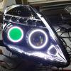
Hodaka Posted November 26, 2016 Author Share Posted November 26, 2016 Sooo... it's been a massive struggle, but 9 months after buying the headlights, I've finally managed to finish modifying and installed the headlights! I'll keep this particular post as short as possible, as doing a full write up on the entire process would be... loooooong! I'm on the fence whether or not I'll do a full write up, but it will be next year before I have time to type that up even if I do decide to go ahead, as I'm pretty busy until then. Anyhow, first of all I guess before and after pics of the headlights: Before After The modifications carried out to the headlights include: Internals - Painted stain black Halos - The original ones weren't a full circle and were very dim, so I replaced them with COB LEDs. I've added auto dimming, so it dims when the sidelights are on (dim level adjustable via a potentiometer) Sequential indicators - These are in the 5 holes below the indicator. It's a bit low "resolution", if I can describe it that, but I prefer it over the DRLs that were originally there. 5 DRLs + 2 halos per side IMO is a bit too much LED indicator - Although not depicted in the image above, I replaced the indicator with an LED bulb as the one shown above was a bit dim for my liking. Also using an LED meant that I could colour match it to the sequential indicator LEDs. Lastly, the fact it removes the fade in/out of incandescent bulbs was good considering the sequential indicators below. Bulb + ballast - These were replaced with newer eBay specials. The bulb I chose was 6000K. Projector - These were replaced with Mini H1 projectors Demon eye - Added demon eyes with a power switch in the cabin, as I won't be running these on a daily basis Here's a pic of the entire set up, prior to installation: Not the best pics, but here's how it looked after installation: The RGB demon eye: With these particular headlights, the adjusters move a bracket that holds the projector & high beam reflector. Therefore the shroud for the projector doesn't move with it, hence why the demon eye above isn't centered within the halo. A tad annoying, but not too big a deal. Oh also the headlight lens above is just dirty, it's not super scratched up. The reason I switched out the projector is as I realised how terrible the previous ones were. I'm not sure, but I think they were halogen projectors with H1 PnP HID kits in them. The light output was very uneven, and there was quite a bit of glare above the cut off. At the time I was still unsure if it'd be an improvement, so I bought some generic Mini H1 projectors from eBay. It required some tuning (adjustment of cut off shield, shimming bulb etc...) but here's a comparison of the 2 projectors. Needless to say, I went with the above, which is the Mini H1s: One of the problems I originally faced (in my previous post in March?) was that the headlight output was aimed sky high. I think that just an issue these headlights (Junyan/Spec D Tuning) face due to the way they were designed. During the installation I aimed them down. The driver's side was adjusted without any issues, but on the passenger side the projector hit against the plastic housing and bent the bulb holder. This had to be fixed, so for a week I ran a mismatched pair of headlights. Anyhow here's an output show of the headlights during this time. You can't really see the OEM projector output anyway, so it shows the output of the new headlight pretty well: I fixed the passenger side headlight by modifying the housing a bit (and using a toilet float ) and installed it. Here's my current output. As you can see I've messed up the rotation of the projector, so that's next to fix!!! I'm really busy until the new year, so I'll have to grit my teeth and bear it for now. In the meantime, I've aimed the headlights lower to prevent blinding oncoming traffic. That pretty much concludes my quick update! Next in line is to sort that passenger headlight rotation (another round of opening up the headlights...)! On a kind of related note, I accumulated a mini collection of projectors during the above... Not shown above, but I've also got another set of Mini H1 projectors, RX8 headlights (pair), E46 headlights (pair), and a single Porsche 981 Boxster headlight... Quote Link to comment Share on other sites More sharing options...
ZEUS Posted November 26, 2016 Share Posted November 26, 2016 Very nice work Hodaka, good to see the results Quote Link to comment Share on other sites More sharing options...
Hodaka Posted November 26, 2016 Author Share Posted November 26, 2016 Very nice work Hodaka, good to see the results Cheers Chris Been a hell of a journey, though still not 100% finished! 1 Quote Link to comment Share on other sites More sharing options...
ZEUS Posted November 26, 2016 Share Posted November 26, 2016 Very nice work Hodaka, good to see the results Cheers Chris Been a hell of a journey, though still not 100% finished! You ain't kidding, all the projectors on the shelf made me laugh. Sort of thing I'd do ! Quote Link to comment Share on other sites More sharing options...
Hodaka Posted November 26, 2016 Author Share Posted November 26, 2016 all the projectors on the shelf made me laugh. Sort of thing I'd do ! Haha yeah, I think they're pretty cool so wanted to display them rather than storing it out of sight! I don't think any of my friends share the same enthusiasm though On a different note, there's like 16 individual shelves and that's the only one I've been allowed by the wife! Quote Link to comment Share on other sites More sharing options...
ZEUS Posted November 26, 2016 Share Posted November 26, 2016 On a different note, there's like 16 individual shelves and that's the only one I've been allowed by the wife! Welcome to my world! 1 Quote Link to comment Share on other sites More sharing options...
Hodaka Posted November 26, 2016 Author Share Posted November 26, 2016 Haha (I'm crying inside) 1 Quote Link to comment Share on other sites More sharing options...

Recommended Posts
Join the conversation
You can post now and register later. If you have an account, sign in now to post with your account.