


V1H
-
Posts
320 -
Joined
-
Last visited
Content Type
Profiles
Forums
Events
Gallery
Store
Everything posted by V1H
-
Hi @m4nn13 I’d be interested, too, if that 30% discount still applies. I might be 2 yrs late though Best wishes
-
PREMIUM CONNECT INFOTAINMENT Upgrade - STAGE 2 I have now upgraded my stock infotainment system with an Android unit. I purchased it through @StormtrooperZon the forum. Left: OEM versus Right: Android (with AGAMA app) What's in the box: The Lsailt Android Multimedia Video Interface [#LLT-YF-VER5.9.5] runs Android 7.1.1 (pre-installed with a number of typical apps) on an with2 GB RAM and 32 GB ROM. It integrates with the OEM infotainment system (incl BOSE® sound) and uses the stock Touchscreen. The unit supports Mirrorlink/carplay/dongles/phones, microSD, USB, GPS, Bluetooth, WiFi etc. You can switch between the OEM and Android infotainment system any time by pressing the BACK button for 2 sec. The Android system includes the multimedia unit and a bunch of cables of which I currently only used the following four: 1) Screen splicing LVDS cable 2) GPS antenna unit 3) main power harness (splices into the stock radio unit's 20-pin and 32-pin cables; and has a 3.5 mm stereo jack connector for SOUND OUT and is important later, among stuff I didn't use e.g. Sound In, rear Camera 12V O/P, mini-speaker) 4) 3.5 mm jack-to-USB converter The remaining mini-speaker, USB cables, DTV/V OUT and AV/CAM IN harnesses I didn't currently use. Installation: This was a bit of a learning curve but @StormtrooperZ was very kindly supporting me with hints and tips First, removed the dashboard trims and remove the touch screen and pull forward the radio/CD head-unit. That's all easily done with a handful of screws. Place the Android box on top of the head-unit (Velcro pad included) as it's slim enough to just about fit snug into that tight space. Connect the main power harness (3), which will remain stuffed behind the head-unit when reinstalled, and route the 3.5 mm jack cable down and out, past the gear lever toward the armrest. The screen cable (1) routes upward and plugs into the stock (grey 4-pin) screen cable (the bigger white stock screen cable stays untouched). Connect the GPS antenna cable (2) and stow the GPS unit away. I shoved it higher up behind the screen and beneath the triple gauge cluster. Reinstall the radio head-unit with the Android box on top, the touchscreen and the dashboard trims. In order for the Android system to play sound though the car's stock speakers (BOSE system) you basically route the Android's SOUND OUT cable to the USB-AUX I/P ( IPOD) inside your armrest. That's what the 3.5 mm jack-to-USB adaptor (1) is needed for. It's not as tidy as the other harnesses. So I ran the 3.5 mm audio cable beneath the gear lever trim into the armrest compartment from beneath through a hole big enough such that the USB adaptor plug would fit through: (I added a short white extension lead that I had lying around) View from underneath: Operation: When the car is switched on it is important to change the radio's input mode to iPod with the DISC-AUX button. Then, as mentioned, you toggle between OEM and Android infotainment system by pressing the BACK button for 2 sec. The default home screen of the looks like this: After connecting to my home WiFi (car sat in my garage; else you could created a WiFi hotspot on your phone and connect this way) I downloaded the 'AGAMA Car Launcher' by Altercars from the Google Play App Store and set this to my default home screen and unlocked the full version ($1.99). The new look is what's shown at the top of this post The AGAMA web page also has user instructions on how to associate the (initially empty) App shortcuts on the home screen with your favourite Android apps. I'm still learning Android, my first ever Android device, but I recognised a few common apps like Google Maps for the Navi, TuneIn for the Radio, etc. The customisable five presets of the AGAMA home screen are Radio, Navi, Music, Phone and Internet, each having their subfolder with up to 5 configurable apps. You can now browse the internet and YouTube, watch videos in the car and whatever you want to do. Later I want to install the TORQUE OBDII app and look like a GTR dashboard
-
HELP: Sidelights & Just One Taillight Not Working
V1H replied to davidv10's topic in I.C.E & Electronics
Looks like you blew a fuse #71. See this post: Hope this helps PS: Afaik, my 370Z has no tail light sidelight LEDs -
HELP: Sidelights & Just One Taillight Not Working
V1H replied to davidv10's topic in I.C.E & Electronics
Can u specify which bulb of the driver side tail light isn't working anymore? Is it the turn signal or reverse light? I'd expect each tail light to have their own fuse, so that when one side fails the car can still drive with the other side working rather than all being pitch black. there might be more fuse to be checked. There are fuse boxes by the gas pedal, too. Pretty sure it's merely a matter of finding that blown fuse and all should go back to normal -
HELP: Sidelights & Just One Taillight Not Working
V1H replied to davidv10's topic in I.C.E & Electronics
Hi @davidv10, looking at your two adapters I notice their contact wires aren't bend in an identical fashion; might one of them simply not give electrical contact when plugged into one of your T10/168 sockets (front parking light, or rear license light? Swap over the adapters on a working light and see if the other suddenly doesn't work anymore. Can't think of any other good reason, given that the fuse is fine. -
PREMIUM CONNECT INFOTAINMENT Upgrade - STAGE 1 OEM navigation maps update By clicking Info on the Infotainment system and entering the menu Navigation Version, one can read out one's ... errr ... Navigation Version. My MY2013 showed from factory: which I updated today to: by installing a set of five DVDs of the Connect Premium (X9.0) EUROPE V7, which I ordered from the Nissan Navigation Store [#T1000-27465]. They'll also provide you with an activation code that's unique to your VIN and Unit ID (displayed when you click Info, then menu entry Map Update). The install took about 4 hours. The new maps are by HERE Maps and are supposed to add about 1.5M km of road, 275k one-way-streets and 449k turn restrictions.
-
As I had to cover two small holes from my previous two gauges on top of the meter cluster I bought the Motorsport Auto Carbon crown meter cover [#50-1915] from the Z-Store. It's a simple slip-on carbon cover with very good fitment. Naturally, I love the looks but hope I won't get too addicted to carbon stuff - it costs too much There appear to be two options out there, some covering the central Rev Dial with carbon too, like the EVO-R cover, but I wanted it uncovered since I skinned my Rev Dial in red. This is the only reason I went with the Z-Store and had to deal with import duties.
-
Hi @StormtrooperZ i’d be interested in a unit too. Cheers
-
Thanks Nick, no worries!
-
Hello, last couple weeks I have decluttered my dashboard gauges and swapped my triple gauge cluster for 52 mm all-LCD-style Prosport EVO gauges (there are green/white and red/blue versions) with the red ones blending into the Z interior theme very nicely. My plan was to swap the gauges as follows: I sourced my EVO gauges from R-Spec Performance Products (UK). The Vac/Boost gauge is the mmHG/PSI version (#216EVOBO-PSI) and comes with a 2.5 bar MAP sensor, which I hooked up to my intake plenum. The Oil Temp gauge is the Celsius version (#EVOOT-C) and comes with a 1/8-NPT temp sensor that screwed right into one of the spare threads on my AAM oil pan spacer. I took liberty and checked its R(T) response and it's different to the stock oil temp sensor. The AFR gauge I bought is the narrowband version (#216EVOAFR), which I chose purely for cost (£56 versus £193 for the wideband version) but adapted it to function as wideband gauge. I reused my existing AEM UEGO controller with its BOSCH LSU 4.9 sensor (very precise). It has an analogue 5V output, which I feed to the EVO AFR gauge after some electronic conditioning: a simple electronic circuit converts the 0-5 V (WB range) into 1-0 V (NB range) in a linear fashion. Because the signal conditioning is quite specific to my case I'll skip technical details. It cost me some extra hacking and customising but saved me some pounds... I managed to extract the single-piece PCB of the stock triple gauge cluster through their three little dash trim openings. To my amazement they were still working afterwards (only the plastic enclosure had to be destroyed). But I had no use for them anyway. I only reused the 'top hat' covers for an OEM look. The EVO gauges fitted very well after minimal trimming: With the new EVO gauges in, the old AEM AFR and vac/boost gauges sitting on top of the meter crown cover became obsolete. The clock is shown on the sat/nat screen anyway, and the battery voltage I can display on my GReddy TOUCH OBD2 gauge on the right hand side. So, no information is lost, just de-cluttered. (I ditched the GPS speedo above the Rev dial a while ago) Close-up of the new EVO gauges EDIT: Since the central dash trim was off I touched up the start button with some Dupli-Color Metal Specks Retro Red (#MS300). I've been toying to buy the red NISMO start button trim for a long while but won't do it now anymore (sorry @Adrian@TORQEN)
-
Hi all, here some pictures of my Torqen Big Brake Kit - XTREME (fitted on 20") 2-piece rotors, 405 mm (F) and 380 mm (R) Calipers: 8-pot (F) and 6-pot (R), red anodised #AN2 Torqen sport brake pads S/S braided brake lines Approximate size comparisons: Installation under way: Before - After comparison: Close-ups: And wheels in motion:
-
Installed some orange 'mood lights'... These are electroluminescent (EL) LED lights (incl. 12V DC inverter, which actually runs them at a couple hundred Volt AC, but milliamps) [Ebay]. They were very easy to install. I got inspired by this youtube install video. For the driver side door cart I simply spliced into the light blue (12V IGN) and black (Gnd) cables of the window controls harness. For my center console mood light, I spliced into the green (12V IGN) and black (Gnd) cables of the seat heater harness (under the cup holder unit). This way, the mood lights light up when ignition is ON. PS: The passenger door I haven't done yet; there is no 12V IGN available and it'll require feeding some power from the cabin to the door.
-
Finally both tail lights completed and installed. Happy I can finally move on. lol
-
It's been a couple months coming, the work and effort was enormous. I modded my 370Z tail lights! I've long longed for a more modern design; the 'individual LEDs' look doesn't quite fit this time of age anymore. There are however, as we know, no commercial aftermarket lights available, in part due to the fact that the tail light cannot be opened (unlike the headlight). I wanted from the mod sequential turn signals and deep red tail lights (new breed of Merc, BMW, Audi, Porsche) Brake Light First I migrated the stock Stop light over to the turn indicator, making it dual-function via amber/red switch-back LED T20/7443 bulbs [US Amazon], plus 7443 socket adaptors [US Amazon] (the stock turn bulb is only two-contact T20/7440). The 7443 socket teeth needed a bit trimming to fit the light housing. Tail Light My research into the deep red came up inconclusively but I believe it's a LED with around 660 nm wavelength instead of the more orange-y normal red of 620-640 nm. I searched long and hard to find 660 nm red LED flexi strips and went through a number of disappointing purchases, all of which turned out to be the normal red. The only workaround I found was to buy 'Hydroponic plant grow light' led strips, which are specifically stated to combine 660 nm red and 460 nm blue LED chips in ratios from typically 3:1 to 8:1. So I bought 8:1 660:460 grow led strips, which I specified to a double-row of 3528SMD chips, a density of 240 LEDs/m and power consumption of 24 W/m [#0.5M-HK-15MM-F3528PG120-NW-8:1-12]. I then removed the blue LEDs from the strips (there was no option of only 660 LEDs) ...et voilà! To avoid varying brightness and power consumption with changing car voltages I decided to buy two PT4115-based LED drivers [Ebay] to power my deep red LED strips at a constant current. First I reprogrammed the driver's output current from 830 to 300 mA by replacing the two original current-setting 1206SMD resistors (R200 and R300) with a single R330 (0.33 Ω, 1%). The PT4115's output current is set according to: I = 0.1 / R, where here R are two parallel resistances, i.e. R = R1 x R2 / (R1 + R2). This way, each LED strip consumes 3.3 W and not get too hot. Also, powering my deep red LEDs at 300 mA requires the driver to apply about 12V which is guaranteed to always uncut my LiFePO4 car battery (>13 V). It's important that the driver's supply is always greater than it's output potential, else the output current would dip. Now the hardest part, opening up the tail lights... Unlike the head lights, the tail lights are fully fused, i.e. the lens is plastic-welded with the the housing. Prying with a screw driver will simply shatter your lens! What I had to do is buy another pair of used 370Z tail lights off Ebay, which I decided to serve as donors for the plastic housing. My stock lights shall then serve as lens donors (I had them already tinted). I could now carefully destroy the Ebay lights' lenses, that is, break them away bit by bit with drills and pliers and files up to the very weld seam, until the unscathed rear housing was left. The chrome reflectors could then be unscrewed, too. My original tail lights underwent a similar procedure where I'd carefully destroy the rear housing, leaving the perspex lens intact. I transferred over my harnesses and plugs, as well as, the original chrome reflectors, minus the OEM LED assembly for tail/stop. While I was at it, I spray painted my reverse and turn signal housings black (initially flat black, like my head lights, but later decided for gloss black to help with reduced light reflection). Then I fabricated the deep red LED diffusor. I bought and experimented with various kinds of perspex (opal, LED light optimised, etc.) and ended up with 8 mm thick clear perspex with surface frosted finish (least internal loss, great surface diffusion). Custom alu brackets hold the LEDs strip against the hidden end of the perspex, light sealed with alu-sticky tape. With the stock individual LEDs removed from the plastic carriers, I cut out a long 8 mm slots with a fret saw so my perspex LED assembly would slide inside. I also added a 'side marker' of the same 660 nm LEDs where there's an unused provision behind the clear mini lens. They operate in parallel to the perspex light: Sequential turn signal Initially I bought a pair of 3-step sequential LED drivers [Ebay] but wasn't too happy that when each next channel comes ON the previous channel turns OFF again (only ever 1 LED on in sequence of LEDs). Also, 3 steps turned out to be too few. However, a pair of Red/Amber switchback LED strip with silicon flexi-tube [UK Amazon] had a 3-step running turn signal with previously lit segments staying ON, and the controller was a 5-channel driver (BK-ZX-6L). I just had to add 2 cables to the 4th and 5th output! This is a test clip (don't mind the blue LEDs that were leftovers of said hydroponic light): The actual turn signal will be made from yellow 12V 2W COB LED bars, one of which i cut in half for the 1st and 4th signal, and 3M taped all to the 'staircase' plastic carrier, and holes for the wire feed-throughs. On the clear plastic screen that goes on top of it I made four cut-outs to accommodate each a perspex diffusors in the next step, and some alu-sticky tape on select locations to suppress light bleeding. I cut out a tiny mirrored letter Z, stuck underneath the 4th diffusor, so it turns the right way up in the chrome reflection underneath. The diffusors were slotted in and glued in place with epoxy. All wired up and routed to the original PCB, which I stripped of all its its components to use as 'carrier board' for my LED drivers (PT4115 & BK-ZX-6L). Put everything back together in reverse order of disassembly. Will still need sealing, probably clear silicon. Don't forget to reuse the Silica gel pack that sits inside every light housing to prevent condensation! Driver side done .... Passenger side to follow... aaarrrggghhhh
-
1. andy James PAID 2. Sebastian PAID - Track 12.40 3. Stephanie 4. Andy_Muxlow PAID 5. SHEZZA PAID 6. Silverthorn PAID 7. Cs2000 PAID - Track 14:40 8. nissmoandy PAID 9.Paul K - will be sorting Payment this week 10. V1H PAID
-
I chopped up my EVO-R LED Fog/Brake light because the LEDs were too dim for me. I binned all parts except for the plastic case and built a new light from a red 5050-SMD LED flexi strip. The brighter LEDs command a bit more current and run directly off 12V. In contrast, EVO-R light has two 78M05 voltage regulators to power its its 555 Timer and all LEDs with 5V only. Hence, I built a new 555 Timer circuit with 12V LED supply: I bought a 555 Astable Timer PCB [#555 AST KIT] to generate the flashing for the brake light (freq and duty cycle can even be trimmed). But this circuit switches Gnd, and to make an easy compatibility with the solid Fog light, i.e. two separating diodes (SS24), I needed a switched 12V (like the original EVO-R circuit did it). So, I added a P-MOSFET (I had a IRF9520 lying around) to the output. Took me a little moment to figure out that it must be p-channel, not n-channel, and how to hook up a MOSFET; haven't had an electronics project in a while I also added the 4k7 resistor to its Gate, called pull-up, to make it a defined default OFF. Again, had one lying around, noncritical value. I sourced two decent diodes and connected them facing each other as shown. This way, when the car applies 12V to the FOG light wire, the STOP light wire cannot see the 12V and potentially corrupt the CANBUS - and vice versa. Also, the factory fog light is a current-hungry light bulb. Thus, in order to keep the CANBUS happy I added the 30R / 30W power resistor (dissipates an extra 5 Watt) parallel to the LEDs to burn more power than needed in modern days and simulate the old days I cut the new LED flexi strip into groups of 3 LEDs (You cannot cut them any other way but multiples of 3) and arranged them on a cut-to-size aluminium plate in a 4x4 matrix. The 17th and 18th LED I wrapped around and behind the base plate. I had to make sure the PCB and power resistors are as shallow as possible to fit into the EVO-R case. Because the new LEDs are really bright, I made a black 4x4 hole mask to better separate the individual LEDs and better resemble a typical F1 style rain light (or, coincidentally a similar style to the A90 Supra! ) This is flashing with all assembled and the smoked lens sealed up with some silicone: Back on the car: Note, the red light halo is not from the Fog light but a hidden under-body LED strip directed at the Motordyne Helmholz cans that comes on together with the tail lights ... OOPS
-
Yes, it fit in straight away with no modifications whastoever. Even the OEM battern clamp works as there's a provision for shorter batteries, i.e. a 2nd lower sitting hole on the fire wall for the short hook. I can make a picture later today. I am not certain on using the battery for daily driving. I think I read the battery has ~2000 cycles? So I don't actually see why you couldn't daily the battery. Just remember the reduced capacity of 30 Ah. That is, don't run your HiFi in Key-On-Engine-Off
-
I also (what I feel) slightly harmonised the exterior looks by capping off the candy-red wing mirrors with EVO-R Carbon Fibre Covers [#370003]. I bought some 3M double-sided tape and stuck them on pretty securely. I think, now the red touch on the car directs one's focus more toward the big Brake Kit I also have a set of darker grey Nismo Door Handles 2018+, which I'll install soon. I got, both, the carbon covers and Nismo door handles from @Adrian@TORQEN, which was of course a delight to deal with
-
Hello, I just upgraded my original 6.5 year old SLA battery with an ultra-lightweight LiFePO4 battery Powerlite PS-30. This 30 Ah model goes for £250, which sounds expensive, but is perhaps the cheapest weight-saving mod there is. Which other aftermarket part saves ~15 kg for just £250? LiFePO4 also lasts ~5x as long as Lead-Acid batteries, and has no memory effect. Cranking power is much greater, too, when comparing like-for-like size. Hence, this small 30 Ah battery has 800 CCA, which is even slightly more than the big old one's 740 CCA rating! As seen in the photo, I added the optional copper terminals to my purchase (#PS-CU0930). The battery comes delivered with an unbranded cheap LiFePO4 specific charger, but I opted to buy a proper CTEK Lithium XS multi-stage charger with trickle function so I can plug in my 'garage queen' over winter and forget. (Just make sure you don't charge your LiFePO4 with a conventional Lead-acid battery charger) Although such a (internally 4-cell) LiFePO4 battery has a nominal voltage rating of 12.8 V, a single cell when fully-charged has 3.65 V, that is, the battery voltage is 14.6 V (100%). I read that a cell charged to 3.4 V is already 95% full, that is, 13.6 V (95%) for this battery. And a conventional automotive alternator outputs around 14.4 V. So, no worries, this battery will charge to about 99% anyway. The battery also has internal short-circuit, deep charge and over-charge protection, as well as, a built-in voltage LED display.
-
Hello, I just upgraded my 370Z's original 6.5 year old SLA battery with an ultra-lightweight LiFePO4 battery: Powerlite PS-30. This 30Ah model goes for £250, which sounds expensive, but is perhaps the cheapest weight-saving mod there is. Which other aftermarket part saves 15kg for just £250? LiFePO4 also lasts ~5x as long as Lead-Acid batteries, and has no memory effect. Cranking power is much greater, too, when comparing like-for-like size. Hence, this small 30 Ah battery has 800 CCA, which is even slightly more than the big old one's 740 CCA rating! As seen in the photo, I added the optional copper terminals to my purchase (#PS-CU0930). The battery comes delivered with an unbranded cheap LiFePO4 specific charger, but I opted to buy a proper CTEK Lithium XS multi-stage charger with trickle function so I can plug in my 'garage queen' over winter and forget. (Just make sure you don't charge your LiFePO4 with a conventional Lead-acid battery charger) Although such a (internally 4-cell) LiFePO4 battery has a nominal voltage rating of 12.8 V, a single cell when fully-charged has 3.65 V, that is, the battery voltage is 14.6 V (100%). I read that a cell charged to 3.4 V is already 95% full, that is, 13.6 V (95%) for this battery. And a conventional automotive alternator outputs around 14.4 V. So, no worries, this battery will charge to about 99% anyway. The battery also has internal short-circuit, deep charge and over-charge protection, as well as, a handy built-in voltage LED display.
-
*** TORQEN *** 370z AAM intake manifold available at TORQEN
V1H replied to Adrian@TORQEN's topic in TORQEN
For pics please look at my build thread. Mine is used in an AAM TT setup, though. I consider this mod rather cosmetic, I would not really expect any noticeable gains until one runs crazy air flow/boost. Install on Page 4: and then some more on pages 5 ff. -
Forgot to upload a couple photos with both Braums fitted:
-
This is an install guide for my BRAUM seats, but will apply to other aftermarket seats, too. You will loose the factory seats motorized seat control and the seat heater function You will save 4 kg weight per seat As you know, I ordered: - pair of BRAUM Racing Elite-X seats, Red Komodo Edtion [#BRR1X-RDRT] that include dual lock sliders - pair of Planted Technology seat brackets [#SB096DR and #SB096PA] I also needed to get extra hardware (per seat): - four M8 bolts and nuts for the Planted seat bracket - one 7/16" UNF nuts for the factory seat belt buckle mounts - one 2R2 resistor to terminate the SRS harness (2.0–2.2 Ω is fine, wattage is uncritical). Passenger seat extras, only: - one 15R resistor (11–20 Ω is fine, wattage is irrelevant) - Nissan Fog Light switch, or any toggle switch of your choice Driver seat 1) The factory seat removal procedure is found in the workshop manual page SE-71. Basically: Remove headrest Slide seat forth/back to unbolt 2 floor bolts behind/in front of seat (M14 socket) Disconnect battery and wait 3 mins Lift seat and unplug OEM wire harness, i.e. 3 plugs: SRS (yellow), seatbelt sensor (small white), motor/heater (big white) Carefully take out the seat 2) You may now test fit the seat bracket, which should line up with the 4 factory bolt holes. Note, the Americans labelled our driver side seat bracket with 'Passenger'. But don't install it! The seat bracket needs to be bolted onto the Braum seats, after you first installed the sliders. 3) Turn over the Braum seat and bolt on a pair of sliders, then clamp in between a handle. The handle must face forward and release the lock mechanism by pulling up (when seated), not down! The sliders have no easy orientation, so look closely at my photo: 4) Use the four extra purchased M8 bolts (facing up) and nuts (facing the floor) to bolt the seat bracket onto the sliders as per photo: 5) Undo the seat belt buckle from the factory seat and bolt onto the seat bracket, reusing the factory 7/16" UNF bolt together with the extra purchased 7/16" UNF nut: 6) Route the seatbelt sensor harness under the seat, which I secured with the yellow factory clips. As for the yellow SRS plug, you could splice into the factory harness before the yellow female plug (photo from step A) and terminate it with a resistor. Or, like I opted to do, cut off the yellow male plug of the OEM seat and reuse it and terminate after that: The termination is done to satisfy the ECU that will look for the presence of a 'working airbag', which is presumably a heater element (the SRS charge igniter) with an electronic characteristic identical to a 2.1 Ω DC resistor in series with a small inductance of 2.6 µH. I appears, from what ppl did before, the ECU is successfully fooled by a simple 2R0 or 2R2 resistor. I ended up ordering a 2R ±1% 3W resistor and a 2.7 µH ±20% inductor - probably overkill. (Would only matter if the ECU test signal was AC rather than DC where impedance deviates from resistance as frequency goes up. Bloody scientist in me ) 7) Place Braum seat into car, reconnect 2 of the 3 harness plugs, bolt down the seat bracket onto the floor. Then reconnect battery if you're done here. If you get an SRS DTC (Airbag dash light) you can reset it with this procedure. Passenger seat The passenger side seat installation is identical, except you have to also deal with the factory passenger occupancy sensor. I’ve seen people transferring over the occupancy sensor by slicing up the factory and aftermarket seats, but with mixed success rates. The occupancy sensor is a bendy pressure sensor that changes resistance as weight sits on it. But that actuation is sensitive to the placement of the sensor and the cushion type/thickness above it (after all, it’s clearly tailored to the factory seat characteristics). I therefore decided to not carry over the occupancy sensor but use a fixed resistor and toggle switch to emulate the sensor actuation for empty/child and adult occupant. The factory seat's passenger occupancy sensor, it turns out, is less sophisticated than I anticipated. As shown in the photo, the sensor simply splices into the wire from the seat belt buckle: I measured the actuation of the passenger occupancy sensor. It acts less as a continuously variable resistor and more as a simple switch, which discriminates between two possible states, only: I) IF seat is empty or occupied by a light weight person (child) THEN resistance = high (150 MΩ – 1 GΩ) II) IF seat occupied by adult weight THEN resistance = low (~20 Ω – 11 Ω) The transition between I) and II) is abrupt. As I slowly loaded the seat with body weight, resistance just jumped at one point from 150 MΩ to a couple 100 Ω and then quickly approaching 20-odd Ω. The passenger occupancy sensor can be approximated by a binary resistance state, HIGH or LOW. I suspect the sensor acts as Pull-up/Pull-down resistor in a simple logic gate circuit to provide the ECU with a Hi/Lo voltage signal. While the sensor states might well be approximated by infinity (open circuit) and zero (short circuit), I decided to emulate the unoccupied state with o.c. and the occupied state with 15 Ω, via an ON-OFF toggle switch. I made a drawing to show the simplicity of all the affairs, no magic or complexity here. In fact, one could even completely ignore the lost Passenger Occupancy sensor, leaving its connector disconnected. The car would merely never nag you to fasten the seat belt when the passenger seat is occupied. Note, passenger SRS is unaffected, and always active in the 370Z. After all, the system cannot distinguish between an empty/child seat with the seat belt unbuckled (R = high) and an adult occupant with the seat belt buckled up (R = high): So, I carried over the seat belt buckle with its wire harness to the Braum seat. As before, I salvaged the yellow SRS connector from the factory seat and terminated with a 2.2 Ω resistor (actually I used a 2.0 Ω resistor in series with a 2.7 µH inductor, but don't bother). Finally I salvaged the white passenger occupancy sensor connector (cut off the sensor's plastic wires) and soldered on a white 2-wire lead, shown here: When I installed the seat with bracket I ran the white lead under the carpet into the center console, since I wan to use a Nissan Fog Light Switch (Ebay) by the cup holder as my toggle switch for an OEM look. The switch is still in transit. Once there, I'll have to solder on the 2 wires with the 15 Ω on one of them. I'll also attach a little custom sticker to cover the fog light symbol.
-
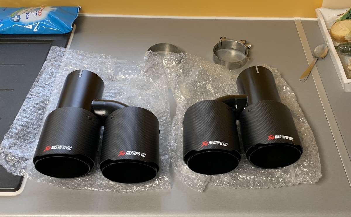
Yes. Although the outer ones are straight 3” whereas the welded-on tubes for the inner ones are bent (h-shape) and a little narrower (i think 2”) You might see it in the attachment.
-
Replaced my exhaust tips for Quad tips. Due to the red diffusor I can, however, only fit h-style (not Y-style) and 3" inlet with max 4" outlets, and a total length of 20-25 cm. Since I didn't want to start welding but something ready I ended up after a lengthy search with Akrapovič-style quads from AliExpress. I was hesitant using the Chinese Ebay place but the quality is decent (if not perfect). BEFORE - AFTER

