350Butcher
-
Posts
780 -
Joined
-
Last visited
Content Type
Profiles
Forums
Events
Gallery
Store
Everything posted by 350Butcher
-
Fast road/Track 350z 3.7ltr HR built
350Butcher replied to 350Butcher's topic in Member Build Projects
Cheers Simon!! Been tons of work, time and money but so good to get back behind the wheel again. Not sure I can do a whole lot more to it but I’ll keep you posted Thanks!! -
Fast road/Track 350z 3.7ltr HR built
350Butcher replied to 350Butcher's topic in Member Build Projects
Cheers! It’s a beautiful bit of machining work and a mega thing to swap cogs with when pressing on -
Pair of sweet Mk1 370z nismo's there!!
-
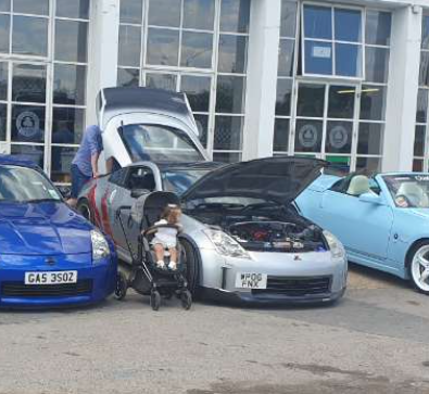
This is a great little capture "Look Dad!...........There's a V8 in this one!!" Some nice Z's in attendance and stonking weather for it.
-
My Z emissions look exactly the same as that.............the unjust £600 tax is very hard to take every year!!!
-
Cheers mate!! Glad I gave it a wash now...........looks decent in the sunshine! Well over 800hp of VQ there!!
-
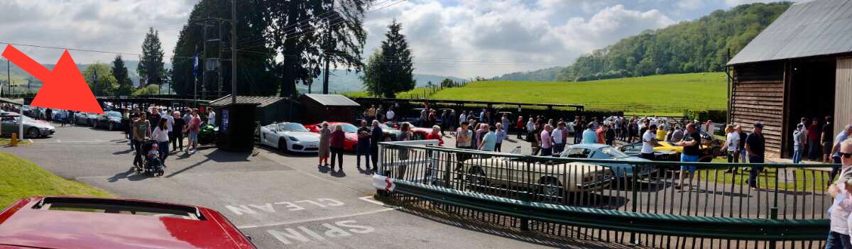
Shelsley Walsh was a great little show and the weather was perfect!! Your Z looked awesome as always!! This one looks nice too!?
-
Fast road/Track 350z 3.7ltr HR built
350Butcher replied to 350Butcher's topic in Member Build Projects
There’s always one!!! Cheers Dave -
Fast road/Track 350z 3.7ltr HR built
350Butcher replied to 350Butcher's topic in Member Build Projects
With engine and 'box now installed came a little cherry on top item for me! I enquired a couple of years ago and it wasn't available, but a quick check on their site and finally CAE had added the 350z to the lucky list of cars they now produce their ultra shifter for and although pricey I just had to have one.......I knew working this new engine and stirring the 'box with one of these would be amazing! They are made to order so it was a hefty wait but it was a pleasure to unwrap on arrival The only downside was the amount of hacked up car dashes I'd seen to get these installed.....I was really hoping that I could make it work on the 350 without too much destruction. Bit by bit I trimmed and refitted the gear surround so's to only remove what I had to and the result was promising With that all in I connected up to the 'box. The shifter is so well engineered the fit is perfect and the install is very simple. The rear cradle that holds the factory shifter is removed for this shifter and it uses the oem universal jointed selector rod directly. It's fully sealed so no smells, water, excess noise etc are gonna come up through it which was good to see also. I was really happy with the results but I had an idea that would make the already pretty special a little more mine and that would be if I could redrill and tap the Nismo gear knob that I have to use on the CAE. With boot refitted too I was so happy with the results..........and to drive with it is absolutely awesome, it connects you to the mechanics of changing gear in the most brilliant and rewarding way -
Fast road/Track 350z 3.7ltr HR built
350Butcher replied to 350Butcher's topic in Member Build Projects
Cheers! Been a lot of work and a long time coming this time round -
Chill out Mr.....Let’s not rubbish this guys build thread eh. My opinion for what it’s worth is that accuracy between the 2 graphs is good and that what anyone would be looking at
-
With any dyno the numbers are largely irrelevant. What you need is a comparison which is what Leon has provided in the graph. His engine will lose out down the bottom and gain at the higher end of the Rev range with strong gains in torque and power above 4K rpm and that’s exactly what the graphs show. If you keep using the same systems to measure on then you have a consistent reading that reflects the gains youre making from where we were and where you are now. I’ll be following your progress Leon.
-
Fast road/Track 350z 3.7ltr HR built
350Butcher replied to 350Butcher's topic in Member Build Projects
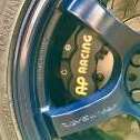
So with the engine back in I always wanted while it was apart so fully sort the clutch actuation as is such a weak part of the HR Z. I did loads of homework and had already decided I was going to throw in the OS Giken STR clutch so that it would be able to soak up everything I could throw at it and not be a weak link itself........... Flywheel mounted with ARP bolts Twin plates all stacked up (with all the balancing marks lined up) And cover plate on and all torqued down ..........So the hunt was on to make something work with that, I looked at technical drawings and options from AP racing and Tilton before settling on the Tilton 1200 series with 44mm bearing. I already had an Extreme clutch kit installed before and the replacement release bearing that comes with them (and other kits) is just an old tried and tested GM unit, the bonus is that it also comes with an adaptor plate to take it from the oem Nissan slave to the GM "saab 9000 type" bolt pattern, the very same bolt pattern used by the Tilton 1200 series!! Now to get all the measurements off the gearbox and clutch kit (as mounted to the engine) as you are looking at the bearing to clutch cover diaphragm springs gap being in the region of 4-5mm when the gearbox is all bolted up.......this is the allow room as the clutch plates wear down. Tilton sell many different height release bearing assembly's to aid with this but I needed the shortest one of the lot plus 2.5mm machined off the adaptor plate to get me where I needed to be! and the result I added a Tilton 7/10" 76 series master cylinder with adapter plate and then went shopping for all the fittings I'd need for piping it all up together Nice stainless fittings Master cylinder mounted Hose run in oem hardline location And onto gearbox with bleed line Attached to new Tilton CSC All bled up on PFC 665 fluid it all works perfectly! Nice feel and engagement.........Well happy with that! Edit: Forgot to add this pic of it all mounted up -
Fast road/Track 350z 3.7ltr HR built
350Butcher replied to 350Butcher's topic in Member Build Projects
No I didn’t get one from the engine dyno run, as said it wasn’t by any means a final thing, it was a quick squirt to make sure it was safe to install. Was amazed by the numbers in the circumstances. I may put it on the chassis dyno one day when it’s fully finished out of interest to see where it’s at. -
Fast road/Track 350z 3.7ltr HR built
350Butcher replied to 350Butcher's topic in Member Build Projects
It’s got all the ingredients to break 400hp really but I was happy at 100/ltr which it’s safely going to be above that and a responsive, keen engine too which is what I wanted to create. All depends on how crazy you want to go suppose. Got to remember these modern bonkers n/a engine are running individual throttle bodies and direct injection too and there’s a point where we can’t install these things on our old VQ’s.............not without a bottomless pit of cash anyway! I did ask about proper set of itb’s for my engine as that would be +25-30hp straight away but when it got to £7k and was still going I thought no thank you!!! -
Fast road/Track 350z 3.7ltr HR built
350Butcher replied to 350Butcher's topic in Member Build Projects
HR plenum flows 420hp..........I’d really love that to be the weakest link. That’s also why I kept the cams as they operate over the best rev range for use and with the gains in torque the increased capacity and compression bring it all works very well. -
Fast road/Track 350z 3.7ltr HR built
350Butcher replied to 350Butcher's topic in Member Build Projects
You've read it or I've worded it wrong but its certainly not peaking there it's just as far as we went and had time to go on the dyno as there were a few software issues. They have been addressed now and its getting better n better with every map tweak.......the way it rips it's not going to be running out of puff anywhere below factory rev limit but I'll probably cap it there for reliability. Cams are the same Tomei 272 degree 10.8mm in/ex as before this bottom end build -
Fast road/Track 350z 3.7ltr HR built
350Butcher replied to 350Butcher's topic in Member Build Projects
Thank you! The stock HR engine is such a goodn that it's crying out to be fully unleashed eh. Never say never, a good man once said to me "if you can undo a nut and bolt then you can do anything"..........the VQ may not be the engine to start on as its so labour intensive but it's really well engineered so its more about patience and taking time with every step than being super complex. Reading your signature you've got a nicely specced Z yourself -
Fast road/Track 350z 3.7ltr HR built
350Butcher replied to 350Butcher's topic in Member Build Projects
Thanks! Good to see yours all up and running too -
Fast road/Track 350z 3.7ltr HR built
350Butcher replied to 350Butcher's topic in Member Build Projects
Cheers! Yeah its a big step on from stock HR and although I've only really tickled it on the road so far its much keener, sharper and more responsive engine than stock HR engine I'll get a vid up when I can get a volunteer to stand road side for me -
Fast road/Track 350z 3.7ltr HR built
350Butcher replied to 350Butcher's topic in Member Build Projects
On the dyno there were a few issues that we struggled with that, without boring you with the whole saga, took quite a few phone calls and couple of days to sort which after all said and done came down to engine latch points not being set correctly in the base map supplied so L\R bank were out relative to each other........not the result we were wanting at this point but as time wasn't on our side we decided to just make the engine safe and usable and get it installed in the car and finish the mapping through remote logging and live use on the road. The engine had already made 370hp at just under 7000rpm with 300 ft/lbs at this point despite being nowhere near finished and with plenty more to come I was pretty happy it! So now it was time to get the old short block out.......... and finally get the new 3.7 engine bolted to the chassis!!.......... -
Fast road/Track 350z 3.7ltr HR built
350Butcher replied to 350Butcher's topic in Member Build Projects
Cheers mate! -
Fast road/Track 350z 3.7ltr HR built
350Butcher replied to 350Butcher's topic in Member Build Projects
All built up it was time to load it all into the van and take it off where it was going to have the Syvecs powered up and an initial base map created to then be run in on the engine dyno so I can install it back into the car all tested and confirmed free of issues........or at least that was the plan!! I chose an engine dyno for the first time this time round as from the second the engine is fired it can be under a varied and controlled load so the rings can bed in properly. There's loads written on the subject for pros and cons, in the past I've run in all the engines I've built on the road but the roads these days are very different to how they were when I used to be able to drive out and be at a pace and load of my choosing, these days I felt I'm going to head out and join a queue behind the 30/40mph brigade with next to no load for mile after mile, not the conditions I wanted so I chose to use the engine dyno this time round..........lets hope in months\years to come it's not a decision I regret. Sadly due to the year and conditions imposed by what was 2020 my dreams of helping out and being involved in the process, hearing it running up for the first time were not to be. I dropped the engine off and returned home to await some news. It wasn't the plain sailing I'd thought it might be in getting it running, wiring being the main reason! Powering up the ecu/engine was another world to me, thank god the guy I used is well clued up on the VQ engine and was able and helpful enough to want to help resolve these things to get it all ready. But we weren't done yet, I made the decision to swap the factory denso lambda's for the NTK L2H2 wideband units, this then meant the base map supplied by Syvecs didn't work so more emails all over the place for a corrected base map till the people who can sorted this out! It was now ready........or was it!? -
Fast road/Track 350z 3.7ltr HR built
350Butcher replied to 350Butcher's topic in Member Build Projects
With all that critical data gathered to pass on to the mapper so they know how far they can adjust the VVT in pursuit of finding most torque/power without any bent valves or worse! By comparison it was now all pretty plain sailing carrying out final assembly. Loads of pics!! To be continued............. -
Fast road/Track 350z 3.7ltr HR built
350Butcher replied to 350Butcher's topic in Member Build Projects
Can't believe its been over a year since posting any progress or updates on the engine! So to continue from Nov '19 I did install the thicker grade 4 main bearings to get the clearances down to where I wanted them so that sorted the bottom end and so I then removed the heads from my current engine. These have been left the same specs so Tomei 272 degree 10.8 lift in and ex. Then the dummy builds began to establish the valve to piston clearances, first up was to find true TDC with my dial gauge, make up a pointer and attached a degree wheel to the crank. My heads were stripped and skimmed, and them torqued down onto the block with some old Cosworth gaskets (same specs as will be used on final build), they were then built up and cam to follower clearances checked, luckily with my existing followers and them from donor engines heads I only needed to order 2 to get both heads where I wanted to be. Then all new 3 timing chains where installed along with tensioners etc and the engine was turned over and I took valve to piston clearance measurements every couple of crank degrees before and after TDC and made a record. I checked clearances at Cylinders 1/2 and 5/6 to make sure there was no variation across the engine. This gave me the clearances as the engine "rest" with inlet cam at zero advance (closest measurement was 6.77mm@8degrees ATDC) and exhaust cam at zero retard (closest was 8.35mm@6 degrees BTDC) I then carried out the same process with exhaust in full retard (the ex cam can just be rotated with a spanner across the flats) which gave a safe closest point of 3.18mm@6 degrees BTDC) As the inlet cam VVT is controlled by oil pressure there's a lockout pin that needs to be removed as to allow you so move the cam to full advance. You have to remove the 4 10mm bolts on the sprocket cover and then remove the pin and spring. This then allows you to move the cam through its VVT travel Now with the inlet cam at full advance the valve got down to 0.8mm@8degrees ATDC!! I wanted to make 2 sets of records that would give me how much advance I could run with running no closer than 1mm and 2mm valve to piston, recording now on the pully with a protractor how many degrees of advance where available before these limits were reached at every couple of crank degrees before and after TDC. As you can imagine this took hours and hours and yes I carried this out again on Cylinders 1\2 and 5\6!!