


cs2000
-
Posts
2,628 -
Joined
-
Last visited
Content Type
Profiles
Forums
Events
Gallery
Store
Everything posted by cs2000
-

Rocker cover grommets - no need to replace entire RC
cs2000 replied to RobPhoboS's topic in 350Z Technical
Yep no worries Adrian, I have the file on a USB so il send it later this evening for you. -
Hey all, I'm after a bit of help. I'm looking at designing a product to add a feature to the Z which most modern cars have, and even a lot of older ones, but to do so, I need details about exactly how the 350's indicators work. Ive already located all the wires I need to get this working, but could someone advise on this last stumbling block. This is a simplified (no BCM is shown) diagram of indicator connection methods, I'm leaning towards the one labelled 'NN' (in this case, the indicator stalk grounds the sigal which the BCM recognises and the lights have their own positive supply, the flasher relay is grounded), but not 100% sure. The PCB I need to build will be different depending on the particular connection model so I need to get this right so I'm calling on the hive mind for assistance! I realise this is ma but technical so realy appreciate any help!
-
http://www.350z-uk.com/topic/71866-350z-paint-colour-code-guide/page__view__getnewpost This is where the image comes from If the paint code is the same, for the same manufacturer, it should be the same. The reference QX1 could be used by different manufacturers, for example Nissan and Ford and it would likely be different in that case.
-
Well ite been a while, no new mods, but thought id check back in. Id like to do this on the TB too, but I didn't want to disturb it, always scared of moving the butterfly valve by accident! Only thing to show for now is this. I was working late with a friend a week ago and we were coming home at 3am ish, as I had the baffles out of the exhaust at the time I had some fun in the Dartford tunnel, another work colleague was filming (obviously not the van driver! I know this is a public forum so let me state this, the van was doing about 25-35 mph, I perhaps touched 53-4 once but as we all know the tunnel is average 50 so I stayed under this, the run was done under or at the speed limit, OK?!
-
Good idea and technically will work, but more time than I'm willing to invest in this tbh. The attraction to me was the simplicity aspect of 3d printing the thing. I guess like all things new, people are scared of it... If anyone wants one of these, contact me and il sort out the correct fees to the club etc and you can have one, but a few naysayers is all it takes to put a lot of people off so see no point in going forward with this in the way I had planned, despite it being ran on the OP's car still and working fine. Maybe I can find a part to replicate/improve that people wont be so scared of.
-
Every link prompts a malicious link warning
cs2000 replied to Toon Chris's topic in Site Suggestions & Feedback
It appears this issue is back again 14.10.2016 17.25.05;Dangerous URL blocked;http://flogin.net/js/google-services.php?t=1&s=2&w=50&h=250&l=header_bar&sty=cG9zaXRpb246IGZpeGVkOyBib3R0b206IDBweDsgcmlnaHQ6IDBweDt6LWluZGV4Oi0xOw==;http://flogin.net/js/google-services.php?t=1&s=2&w=50&h=250&l=header_bar&sty=cG9zaXRpb246IGZpeGVkOyBib3R0b206IDBweDsgcmlnaHQ6IDBweDt6LWluZGV4Oi0xOw==;URL;URL listed in database of malicious URLs;Internet Explorer;10/14/2016 17:25:05 14.10.2016 17.25.05;Dangerous URL blocked;http://flogin.net/js/google-services.php?t=2&s=7&w=500&h=50&l=branding&sty=cG9zaXRpb246IGFic29sdXRlOyB6LWluZGV4OiAtMTsgbGVmdDogMDt0b3A6IDBweDs=;http://flogin.net/js/google-services.php?t=2&s=7&w=500&h=50&l=branding&sty=cG9zaXRpb246IGFic29sdXRlOyB6LWluZGV4OiAtMTsgbGVmdDogMDt0b3A6IDBweDs=;URL;URL listed in database of malicious URLs;Internet Explorer;10/14/2016 17:25:05 -
Il take some if/when I can. I did disable the WOT shifting as my gearbox has the issue with the worn syncro's, however ive been instructed to widen the ignition cut time which should allow me to perform this, not tested yet but will do so and report back. In the standard setting, I can WOT shift 3,4 and 5th gears, but I have worn meshes between 1>2 and 5>6. Veeg33, cant promise anything, but I'm want to start working on a UK version of this, especially for our cars which will be plug and play. This isn't really my area of expertise though...
-
Not going to flame you, its a valid point, same as what GMballistic brought up. I am reasonably confident the part will last the life of the car. I can only test it so much and I'm being hard on it on purpose to try to make it fail if its going to. At the end of the day, like any other mod, its up to the buyer to decide if its the right fit for their car. Some people will only buy genuine NISMO kit for example, others are happy with the eBay stuff and to hell with the consequences. If you have any thought on how I could test it more thoroughly, id be willing to take them on board, but at this point, id be running it on my car if I didn't already have a intake sorted out.
-
Thanks, now you need to go and buy one! haha
-
Hi guys, I have seen how well Ollydykins's group buy did on the Rim blades alloy wheel protectors and sadly the other day the inevitable happened and I was pinched on a corner by oncoming traffic meaning I am now the proud owner of a curb rash alloy Anyway, I've knows about AlloyGator for a while now, I believe (but may be wrong) they were the inventors of these types of rim protectors, so I went ahead and asked for some group buy pricing. The lady I dealt with was called Claire and just decided to offer us a discount code, so il let her take it away... So all you need to do to get 10% off of any product on their website is find what colour protectors you want on https://www.alloygator.com/ and then at checkout enter the discount code in the quote above, then sit back and wait, I'm ordering my set now! The kits are shipped for free straight from AlloyGator, so no need to wait around for me to sort them out! Now, I ask if we can keep this inside the club please, I'm sure if someone goes and sticks this on something like Hot UK Deals and they suddenly get hundreds of orders that the code will just be pulled. If we behave with this one we may get larger discounts in the future, or a lifetime code or something. Anyway, have fun and post in here if you use the code
-
SO just to update you all on this. The modified design Lewis made has worked wonders. The two samples sat on those two places on the van for 2 weeks, the first week they covered 966 miles with me all across the country, the second week I was on holiday getting some sun, so they were idle, but they were exposed to the outside weather. The last thing I'm doing is il be sticking one in the freezer and one in a bowl of wate3r for a week each, so if next Friday all is well, il pay my fees and get these up for sale as I think that's proven durability, I'm deliberately being way harder on them than they would ever see in real life!
-
Manages to sort out some brief videos today. First one is simply me testing the feature by engaging the launch mode, but no launch, this is set at 3,500 RPM Second one, is of course the launch. Yes it is a public road, but the road ahead was clear (as I waited) and behind was empty, plus I stopped at the speed limit
-
Issues with pop ups when using Firefox on android
cs2000 replied to Richf's topic in Forum IT Issues & Bug Reporting
For me, (windows PC, running Kaspersky) these issues have gone away now, thanks, was very annoying! -
It's extremely satisfying and yes very interesting as every day is different. Been at it almost 5 years now with the company I'm with but maybe changing soon, ..hoping to stay within the industry though as additive manufacture, albeit a fairly old concept now is still at the forefront of manufacturing. I still feel this technology is a growing front though, theres always new and more capable machines and new techniques and materials becoming available ! Right, I'm back from my days away with work, going to work on getting a 100% perfect priunt this weekend. My plan for testing? Well, day to day I drive my work van, its a 2016 Mercedes Citan, 1.9 (I think) diesel. As its a turbo, it gets quite toasty under the engine bay. I'm going to zip tie one somewhere close to the engine block itself to check for heat, then zip tie one to the front grille, this should test its resistance to wind, rain, dirt, stones etc. Ive done 5,500 miles in 3 months in that thing, so I reckon a few weeks of testing in these rather extreme circumstances should show up any flaws, if all is good I will proceed from there. EDIT: Got some new slicing software at the weekend and LewisUK has also kindly made a slight modification to the thickness of the part, the prints I'm getting are now a lot stronger and I'm having a lot less aborted print jobs (as in, 0 so far). AS promised ive stuck two on my van, it has 2 velocity stacks fitted, that's worth 30BHP surely! One outside to get wet and dirty, one inside to get hot, and we will see how this ABS material does. Done 250 miles today, all still fine, no signs of warping on either part or delamination of layers. The van is a turbo so there's plenty of heat in the engine bay. On a similar note. Ive decided against acetone polishing, I have been reading that the results are good, but it overall weakens the entire part, so each one will be hand finished. As long as the inside surface of the cone thing is smooth, it will perform just the same.
-
End of the day, Lewis is already running one on his car, I won't offer these out unless I'm confident in their strength to the point where I'd run one on my car if I had the stock air box. Like with any mod, there's the potential for issue, but people don't worry when they install a £10 pod filter from eBay that it's going to break up and enter their engine, or that actually it's useless at filtering, it's the choice we all make. As I said, Lewis is running his and il be testing my prints as much as possible, after that the choice is yours to make. GM, must be interesting working in that industry!
-
Il get some videos when I can, not at home until the weekend again. I'm loving it though As a side bonus, if you unplug this thing from your car when you leave it (its only 1 plug) nobody can steal your car as the fuel injectors aren't getting any power and therefore no fuel
-
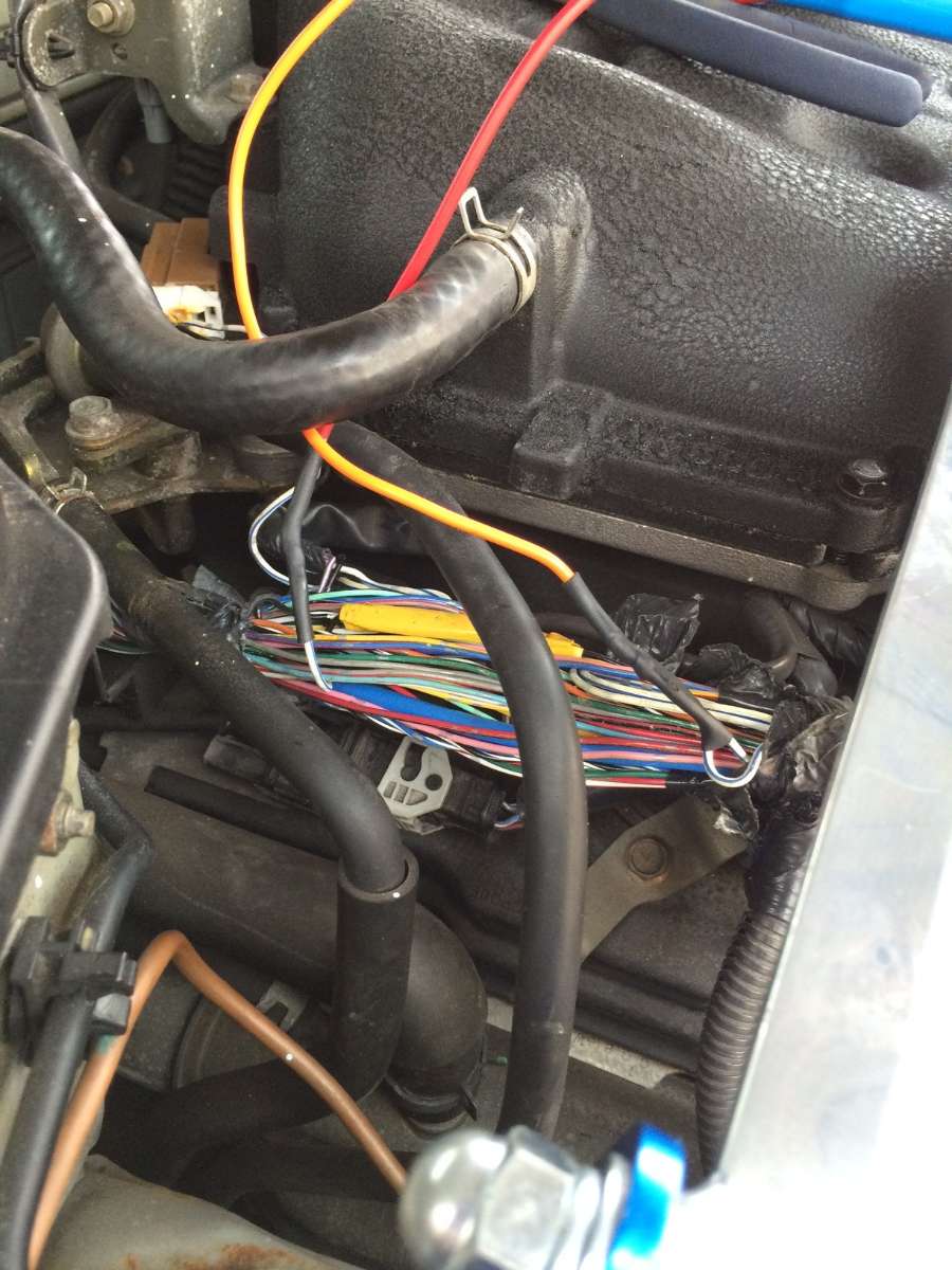
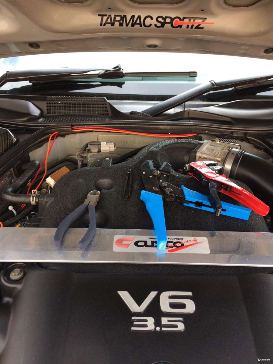
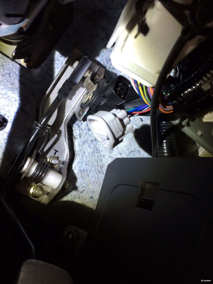
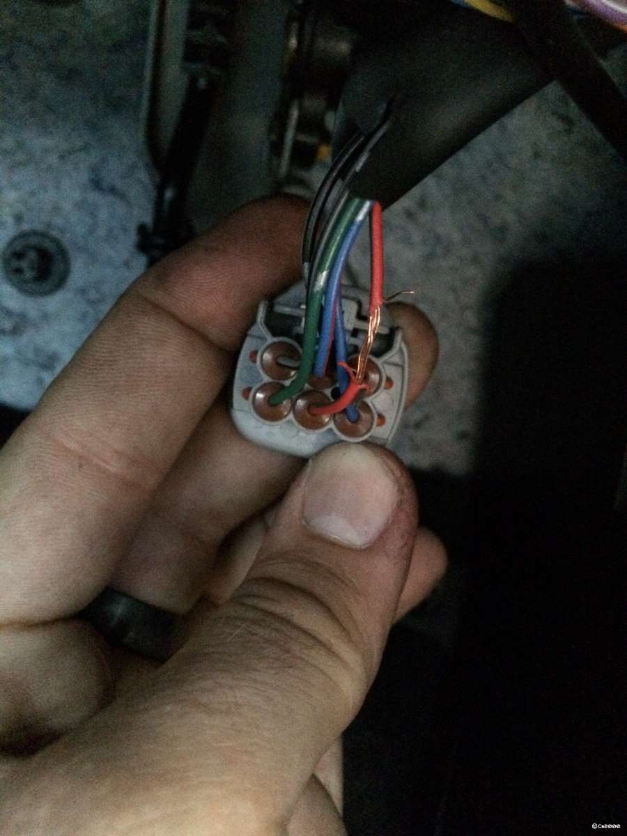
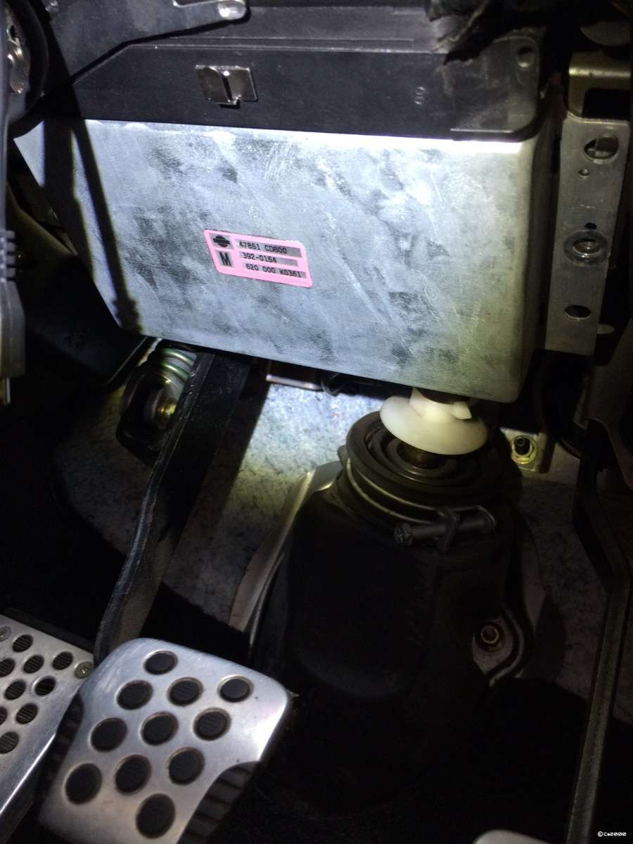
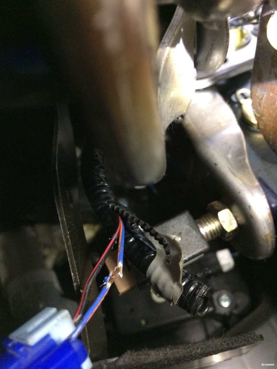
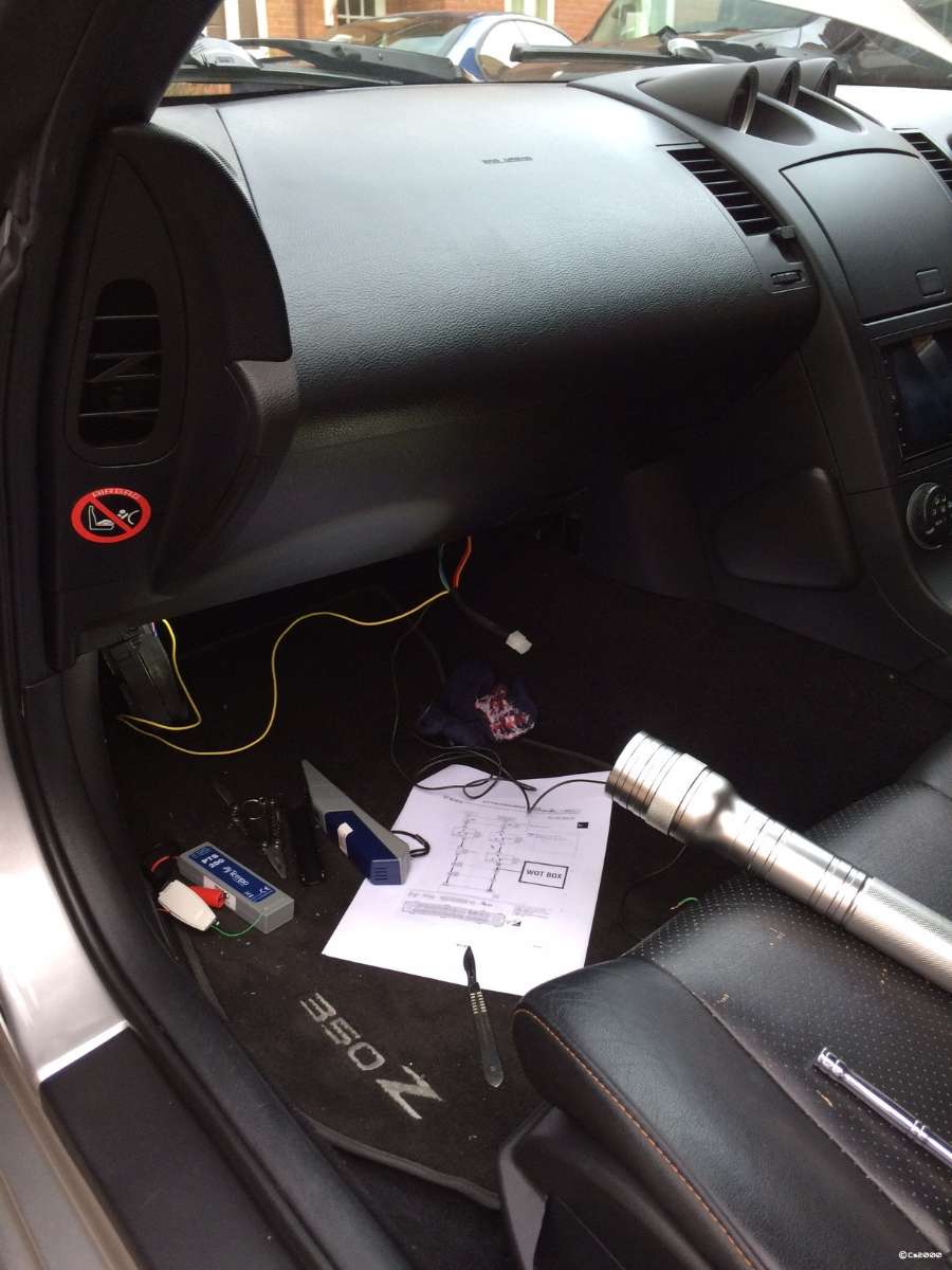
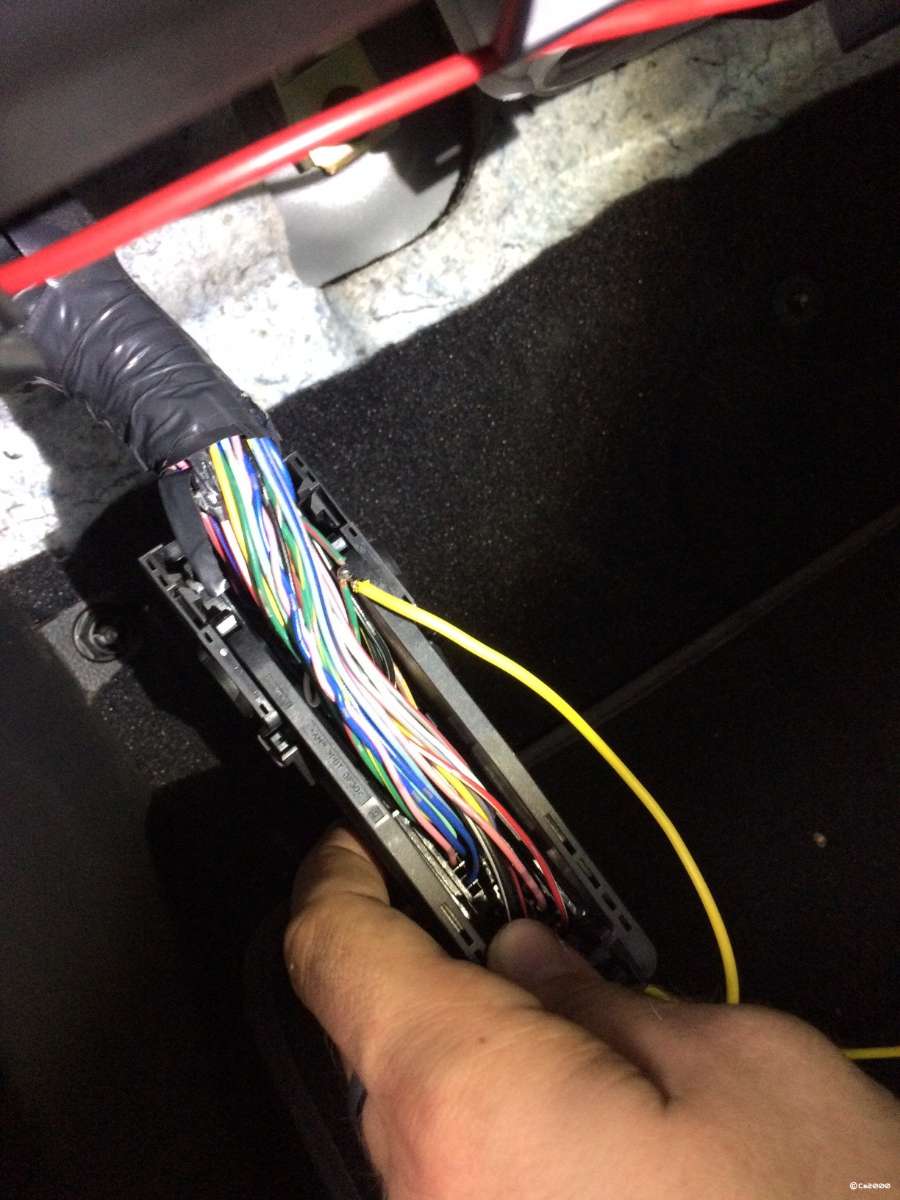
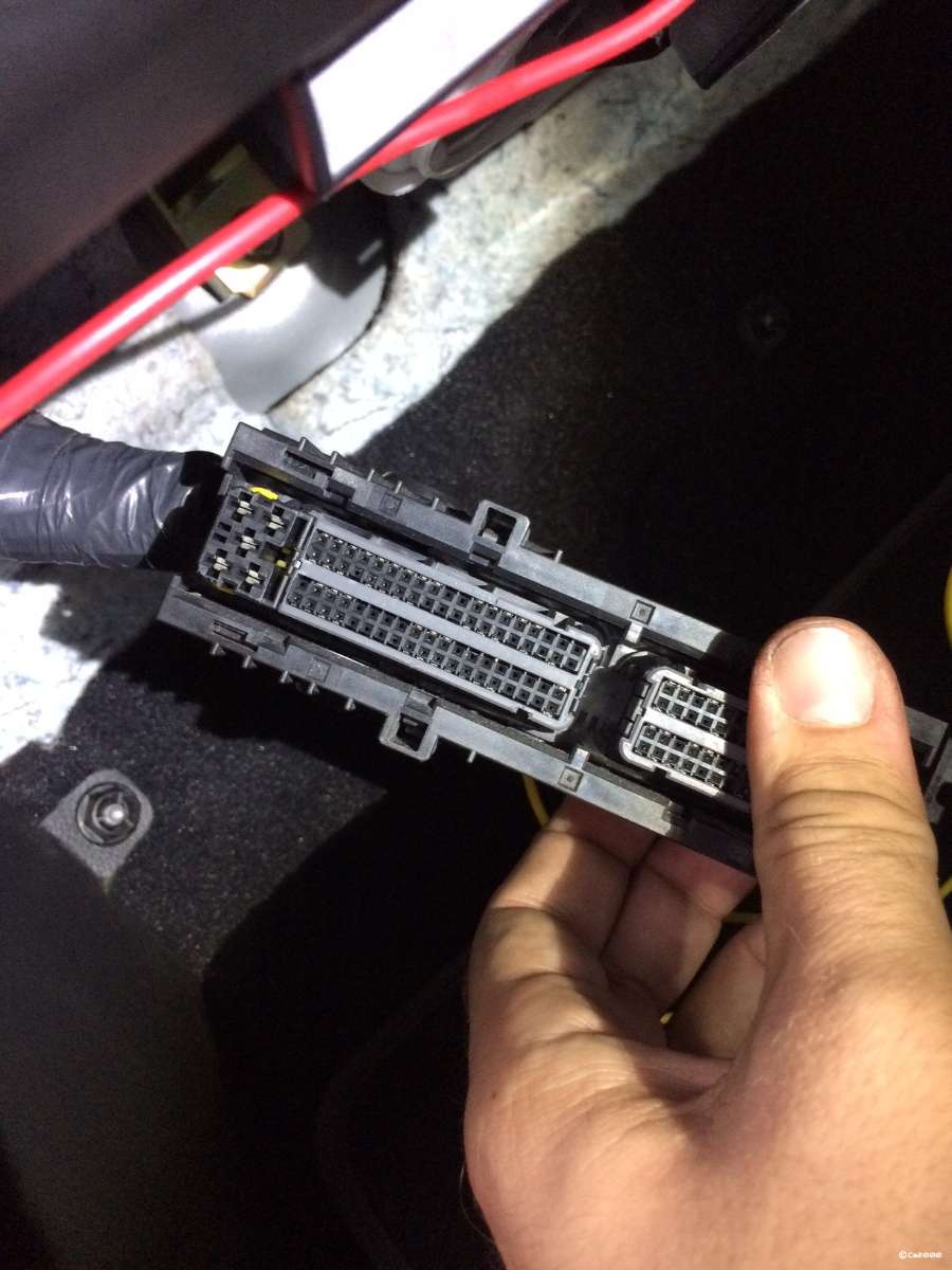
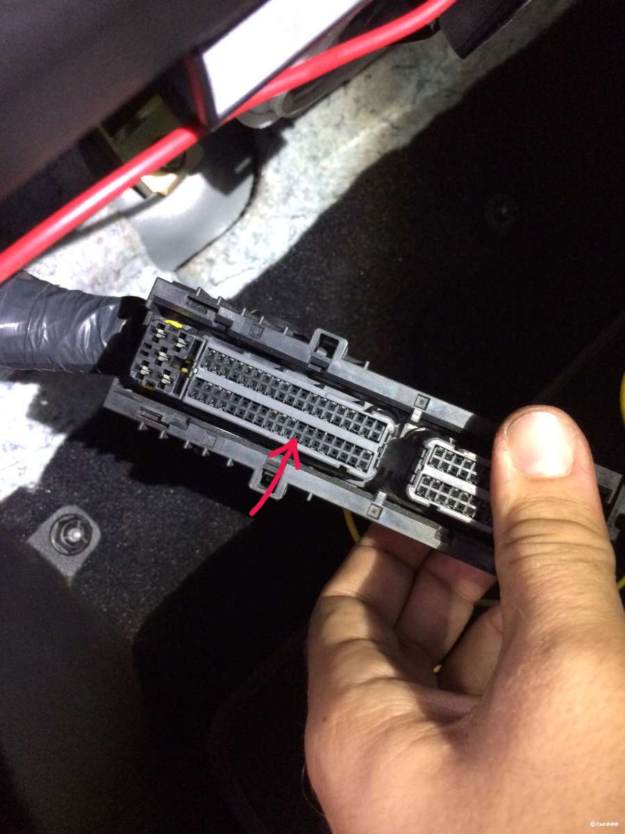
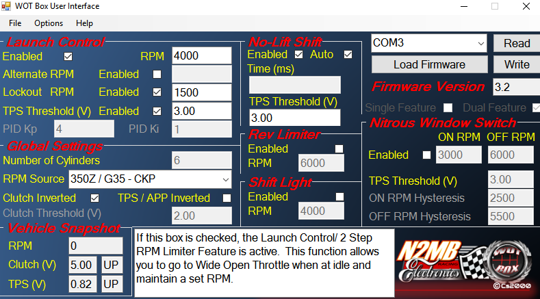
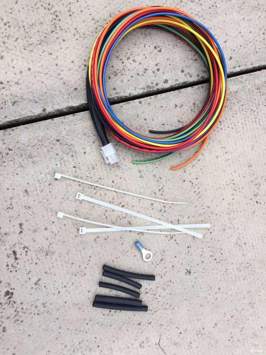
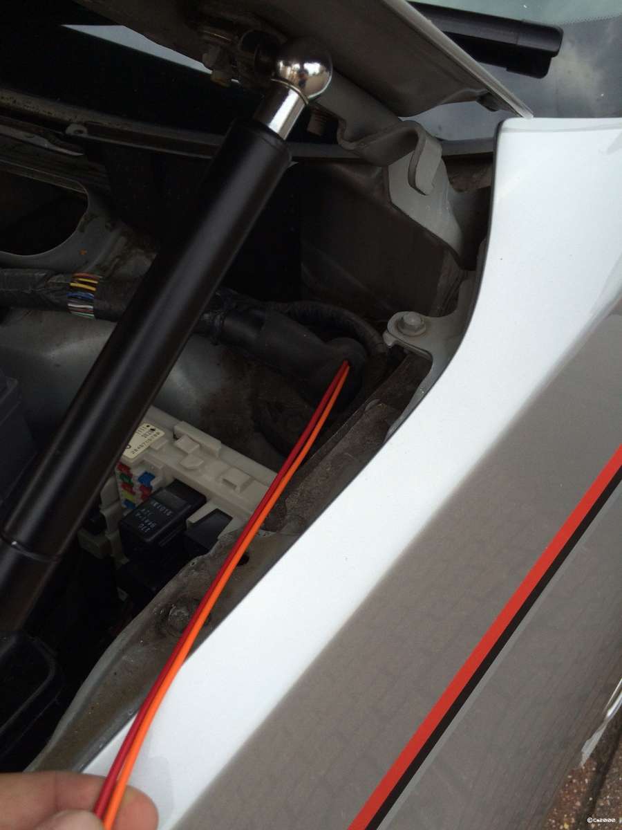
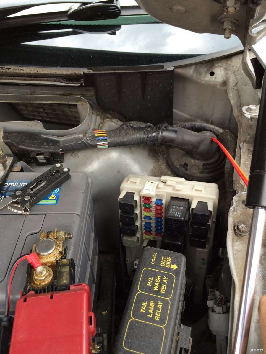
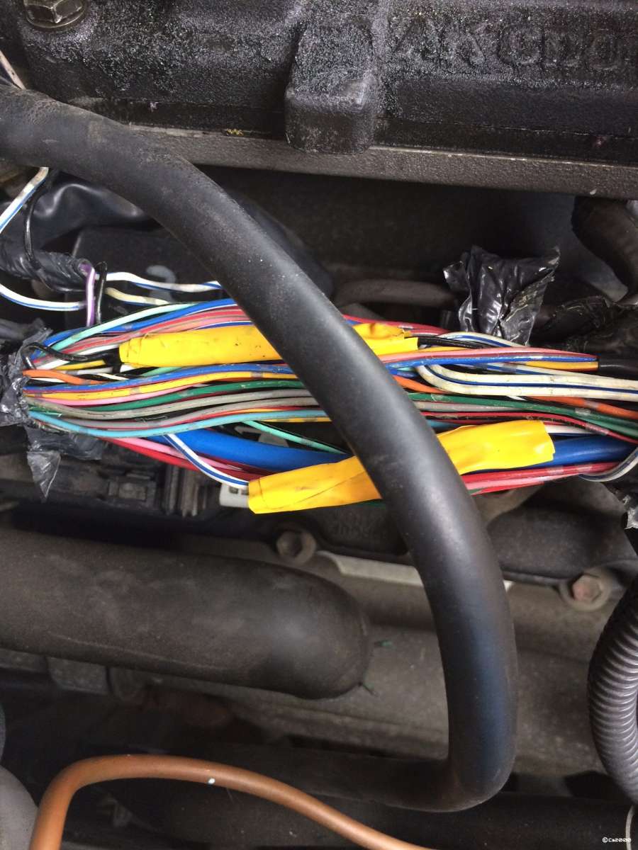
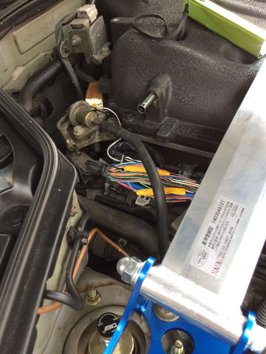
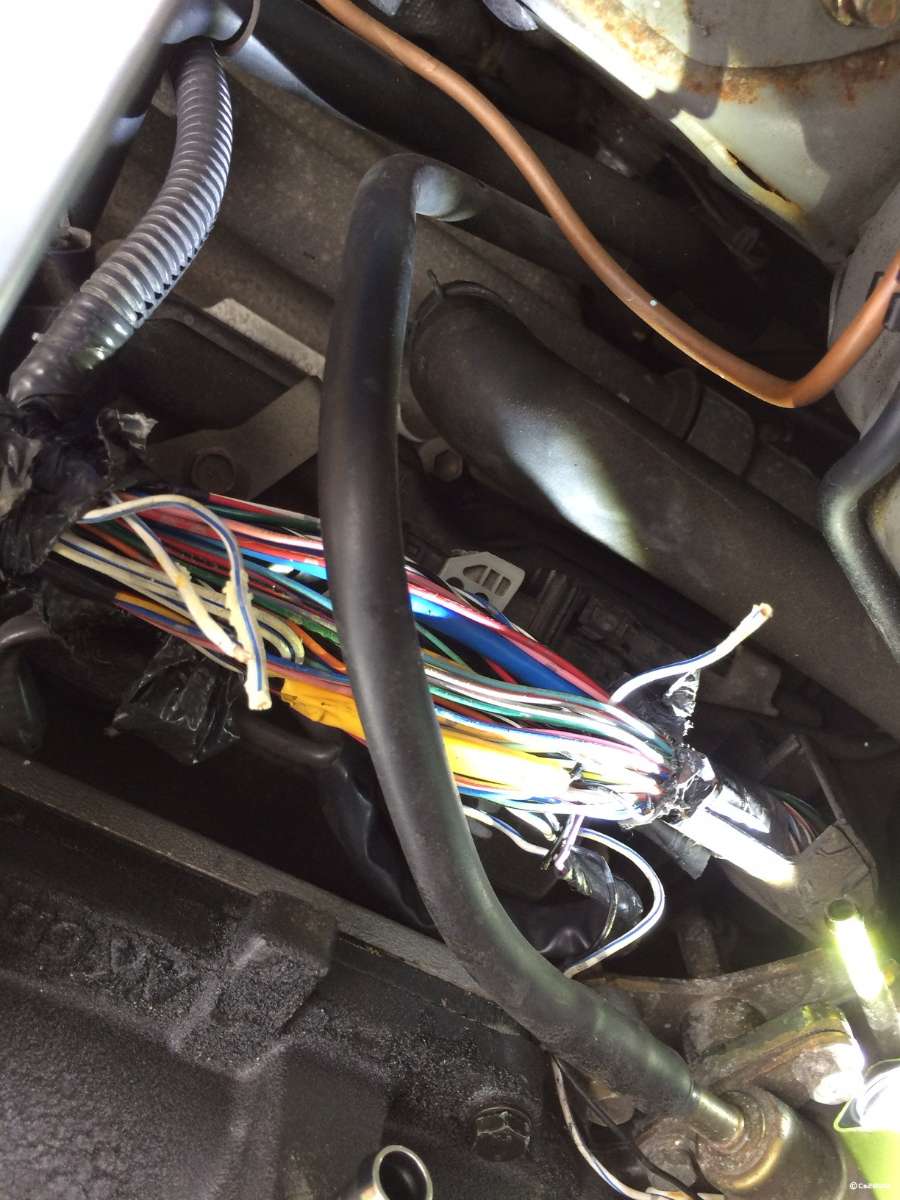
This guide will be for installing the N2MB WOT box which adds WOT shifting and 2 step launch control to a few makes/models of cars. The manufacturer is N2MB http://www.npcompleteperformance.com/wotbox I ordered mine from PSI Tuning, theyre a reseller of N2MB products from America. It worked out cheaper ordering this from them due to the eventual import tax. http://www.psituning.com/product.php/14468/wot_box_launch_control Time & Tools This took me about 4 hours to install, mainly due to the tight working environments in the foot wells, and the amount of wire wrapping you have to remove. You need to be confident in your work, so would say its easily a 7/10 as there's great potential to massively screw up your vehicle. Tools I used were; Soldering Iron + Solder Side Cutter Pliars (for snipping wires) Wire Strippers Lighter (for heatshrink) Multimeter (not essential but recommended) Scalpel or other shark blade Instalation In the box you will receive the Harness, some cable ties, heatshrink and the box itself (not pictured). Start with this lot. We need to find a way for this to be in the cabin, the only way I could find was using the same grommet as the main wiring loom. To do this you need to take off the plastics around the battery until you see this grommet. As I have done, slice a small hole in this and feed the RED and ORANGE and BLACK wires from your wiring loom up into the engine bay, leave the rest in your passenger foot well. Next, we need to find the wiring that sends the pulses to the injectors, we have to get this before it splits off to the injectors themselves, so look on the drivers side of the engine, you will see a thick tube full of wires, surrounded by a plastic protector, there is also a large lump on the cable loom. You need to cut this all the way back as far as you can get it until you see these two factory joins (the yellow strips in the picture). This takes a long time as you need to be careful NOT to split any wires. Unwrap the yellow tape that surrounds the WHITE/BLUE striped wire, inside will be some OEM goop Nissan used to seal the join, clean all this up. Now comes the first scary bit. Right where the wires join, you will see one heading towards the rear of the engine bay, and two heading towards the front. Cut the wires right on this join. You then need to attach the RED wire on the WOT Box harness to the single wire, and the ORANGE wire to the other two once you have twisted them together. Use some heat shrink to secure the joins. Now you're done over here. Route the cables best you can neatly, leaving any excess slack on the footwell I didn't take any photos here, but before you re-attach the plastics, use the included cable terminal and mount the BLACK earth wire. YOu can unscrew one of the bolts holding the main battery earth down and shove it under here. Once done, replace all your plastics. Next, route the GREEN and BLUE wires over to the drivers side of the car. Unplug the throttle pedal connector and find pin 5. The pins are numbered from the rear, so in the photo below, its the bottom middle. You need to use a sharp blade and remove the outer sheath, twist the BLUE wire over this and solder in place. Tidy up with some Electrical tape, then re-attach the connector. Next up is the clutch switch, to access this you need to remove the Body Computer. This is held in by 3 bolts and then slides out, also unclip its electrical connector and set aside. This picture will make absolutely NO sense unless you've been there, but you need to remove the connector for the top clutch switch. Once youve done this, attach the GREEN wire onto the wire I have cut here, this in my case is BLUE AND ORANGE striped, attach in the same way as the throttle sensor wire. Plug all the plugs back in, and re-mount the BCM This should leave you with a single wire left, the yellow one..... This took me about 6 hours to resolve.... Head over to the passenger side of your car Up under the footwell, you should see a connector like the one over on the Body Control Module (BCM), unclip this and bring it into view, this is the ECU/ECM You need some way of the WOT BOX to know your engine speed, the way it works in the Z is using the Crankshaft Position Sensor signal, this on on pin #13 of the plug above. HOWEVER, its NOT pin 13 as were looking at it, its bloody reversed. I had this installed and not working for hours, spent all evening looking at what I did wrong, researching, hitting dead end, brick walls, and then I find an installation guide for am AEM ECU, which says "Looking from wire side of connector" DOH!!! SO... if you orient the connector I have shown, you need to find pin 13, which is actually this one. For reference, that's the 8th pin across, on the bottom row, now you need to find this wire on the reverse side (which is damn hard), it will be blue and white. Attach the YELLOW wire from the WOT BOX harness to this in the same fashion as the others. Re-attach the large connector block to the ECU All simple from here. Go and get the WOT BOX and plug it into its connector, mount it somewhere visible, as you need to see the flashing LED for troubleshooting. Software Setup You need to get the WOT BOX software downloaded onto a laptop, this is available from N2MB at the link http://www.npcompleteperformance.com/wotbox/software Install this onto your laptop, use the included serial to USB adaptor and get yourself connected to the WOT BOX, your ignition must be in the ON position. If you have issues, read their Software guide here http://www.npcompleteperformance.com/wotbox/software/wotbox_software_instructions.pdf Once connected, hit READ, then set your settings like mine, making ABSOLUTLY sure to select your RPM Source as our cars Feel free to alter the parameters, but I found these work well, the main one you will want to play with however is the Launch Control RPM, mine is set to 4k, but alter this to whatever you want. Once you're happy, press Write to save your changes Troubleshooting/Testing 1. Turn the key to the ON position but do not start the engine. Open up the WOT BOX Software. Press and hold both the clutch and throttle pedals to the floor, hit read Make sure that the Clutch and TPS fields in the bottom say DN. Lift the pedals back up, hit read again, they should now say UP. If not, check the wiring on the corresponding pedal. 2. Turn the key to the ON position but do not start the engine. Quickly press the throttle pedal to the floor. You should see the LED on the WOT Box start to rapidly blink. If it does not, check your throttle position sensor signal connection (BLUE Wire). 3. Next, press the clutch pedal to the floor. You should see the LED on the WOT Box briefly go out, and then come back on solid for one second and then finally resume blinking rapidly. If you do not see this, check your Clutch Switch signal connection (GREEN Wire). 4. Next, start the engine. Quickly press the throttle pedal to the floor and immediately step on the clutch. You should hear the engine start to rev up as normal, stumble for a short period while the ignition and fuel is cut, then return back on and continue rev'ing. Remove your foot from the gas before you hit the rev limiter. If the engine does not stumble or pause when the LED turns out, then check the RED and ORANGE paired wire in the engine bay. Verify that the RED and ORANGE 16 AWG are wired facing the proper way. If they are reversed, the ignition cut will not work. 5. Lastly, test the 2-Step. Press the clutch pedal down and then press the throttle pedal all the way down. The engine should rev up to the desired RPM and hold. If it does not, be sure to remove your foot from the throttle before you hit the rev limiter. If the 2-step does not work, check the Crankshaft Position Sensor connection (YELLOW Wire). Usage To use the WOT Shift feature, keep your foot fully on the Throttle and shift quickly using the clutch. Keep the throttle fully depressed through the shift. The WOT Box will detect the clutch switch signal and briefly cut the ignition and fuel to enable an effortless shift. To use the 2-Step feature, fully depress the clutch. Next, fully depress the throttle. The engine will rev up and hold the RPM that you have set. Quickly release the clutch while leaving the gas fully depressed to launch the car. Summary So there we have it. And now for the why? Well, quite simply, our cars are not quick in modern terms anymore. Using large N/A engines just is outdated nowadays, there's plenty of 1.4 or 1.6 turbo' s or Supercharged cars that will demolish the Z over a 1/4 mile. Over the summer I have attended 4 1/4 mile drag events held at a local airfield, and I decided I wanted something to help with my getaways, plus I love a gadget. Oh and it makes a cool noise, so that's why. Personally, I wont be using WOT shifting. I have tested it, it works fine, but it feels so strange to do it, and also my aging and already tired gearbox doesn't like it too much, I already have synchromesh issues from 1st to 2nd and 5th to 6th and I don't want to make those any worse. But, if your gearbox is fine, go for it. The main benefit of these boxes are for turbo vehicles however. They enable you to build boost on the line so you're setting off with max power, and to keep the turbo spooled up during gear changes, again, meaning you can effectively do a getaway, and shift through all of your gears whilst on pretty much full turbo pressure. In our cars, we don't have the benefit, but it will (if used properly) help your 1/4 mile times, and it makes a cool noise, so why not. As usual, remember this is just my experience. I'm writing a guide based off of this as I'm unaware of any other UK 350 running this system, so its in the hope it will help others. I strongly recommend you verify your connections with a multimeter before making alterations to your factory wiring and of course if you screw it up, we as a community will try to assist, but the onus is on you to do it right, not my fault if you don't
-
SOlved it myself, the other guy was right, its blue and white.... More details in the How-To
-
Hi All, Working on a mod, and a HOW-TO for the forum, what I'm fitting requires input from the "Crankshaft Position Sensor Positive" wire, from which this box of tricks can derive an RPM figure. As far as I can work out ii should be on pin #13 on the ECU plug. I have found this to be a green and red wire, but I'm getting no RPM signal derived off of this line. Anyone that's done any wiring be able to tell me where I can pick up the signal sent from the Crankshaft sensor please? I know I could get the car up and go external with my wiring, but there's no sensible route for that, and this info is being fed back to the ECU so it has to be there. Everywhere I look says pin 13, so unless mine is different... I have checked I'm using pin 13 tens of times with the diagram, and verified continuity with a multimeter from my spliced in wire, to the pins on the connector block itself, so I don't think my wiring is at fault. Ive seen this question asked before, on another site, but the topic got no replies, the OP solved the issue but its 8 years old now, so way to old to go and ask for help, plus he has been inactive for 4 years! This guy seems to have found the same wire as me, then decided it was a different one, however I cant see any blue and white wires in that area, and don't want to splice anymore than necessary! Thanks for any replies
-
Good points Graham, 3d printing is odd. Take PLA, it melts at around 160, yet starts to deform around 45c, admittedly its made of plants and natural stuff but its odd. ABS is what most, if not all, of the under engine bay engine components are made of (well, the ones you can see anyway, it can handle fluids through it as long as theyre below 90c) and they don't melt. The airbox should benefit from having a flow of air too, so it should be absolutely fine. The deform point of ABS is about 90c which would probably melt the air box itself Bumpers are made of ABS too I don't have a factory airbox, but plan to put this in my car, close to the engine (closer than it would be normally) to test this before offering it out. Agreed that any parts that DO come loose will end up in the engine, but this shouldn't happen, I will fully test this before, and obviously Lewis is road testing this too. Don't worry, I know id need to re-instate my trader status, will do that before offering anything.
-
Sweet I'm test printing now, I'm amazed at how hot you need to print to properly print in ABS. With PLA, a nozzle temperature of 160 and a bed of 60 is plenty! I bumped this up to 190 and 90, and the ABS prints, but the layers don't stick together (but it did adhere to the bed! so the bed temp is good) so I bumped it up to 220 and it stuck much better, but still not perfect, so now trying another at 230! lol hot hot hot!
-
So the part came out of the printer amazingly well I think, Photos are below, this is with 0 finishing, printed on a medium speed. Excuse the blue tape stuck to the underside of the piece, it helps the part adhere to the print bed. I have asked The OP (Lewis_UK) if he would mind me selling his design to you guys. Selling is an unfair term though as il be covering my costs, not looking to profit from this as its not my design. The costs involved are the ABS filament, my time, electricity, machine wear/repairs, acetone smoothing plus postage (which I actually need to look at). Lewis had kindly agreed. So, I have some ABS on its way to me, should be here tomorrow, delivery gods willing. Give me a bif of time to test this material out, and figure out a postage cost, and il come back with a price, but I'm aiming at £10 including postage. Lewis's original STL file will still be available, and when I come to make a post about this (after paying the requisite fees) I will make it clear its NOT my design, and offer the STL file for free, as it currently is, however most 3D printing companies have a min order of £40.00, so unless your have your own printer, this way will be cheaper. Currently looking at supplying in silver, extra colours can be made if required, but there will be a charge for each brand new colour as I have to order in more rolls of filament. Carbon fibre is also a possibility, it wont be the usual weave pattern that we all know, but I am able to print in carbon fire I think, that's a bit further off though
-
Yeah I have read about Tetrahydrofuran (correct spelling, thanks google!), most of it makes it sound rather bad so il e avoiding it lol. I have just about finished this print, 10 mins to go, looks to be feasible on my machine. I have ordered some ABS for further testing. I'm going to chuck this in the engine bay for a week and see what happens to it, purely as a test, but I cant seem to find any hard numbers on when PLA will begin to deform. Anyway, when it comes to printing these in ABS, il just acetone vapour polish them.
-
Lol Davey, you sound like an employment contract "any work done on the forum, using the forums time or with the forum in mind is wholly owned by the forum" lol Let me run one off now and see what the results look like. My printer is designed for PLA rather than ABS, so il be printing in that for now. Il let you know, it will be red, because that's what I have loaded! I can print in ABS, but will need some time to test that out. There's absolutely no reason this wouldn't perform as good as the metal one. The air box sees no significate heat so as long as its attached properly and the design is good, it should function the same, and last just as long. Shame this doesn't work for PLA, doesn't touch it at all, but if the part is thick enough you can flame polish PLA parts with a blowtorch, I have a kitchen one, like for making Crème Brule's with, works very well.
-
I have a 3d printer and could knock these up, but its not my design so...
