

Hodaka
-
Posts
661 -
Joined
-
Last visited
Content Type
Profiles
Forums
Events
Gallery
Store
Posts posted by Hodaka
-
-
If you stop doing this, and run matched tyres all round you will be fine

Got it, thanks for the pro tips!
I have MPSS on all corners so I can mark that off the check list!

those rear led lights look great! never seen them before makes it look alot newer as i do think the 350s need led's to bring em more up to date
Yeah, I totally agree. Super pleased with them

Looking good, might have to tuck my bumper now.
£5 or so + 10 mins of work - would definitely recommend.
 Just make sure you get a friend to help as holding the bumper up while trying to drill the holes wouldn't be fun I'd imagine!
-
Yeah if you can't find it then I saw a post on here of a member that can possibly make them up.
Here is the link http://www.350z-uk.c... gear finisher
Thanks for the link!
I'm hoping it's in my boot (I have a ton of stuff in there) but if not, that thread will definitely help! -
Yeah I did try doing it that way, couldn't stuff it in neatly though and when I did the stitching wasn't lined up along the top of the handbrake so I gave up!
Yeah it was in the Nismo box behind the sticker. I almost missed mine too when fitting it.
Yeah pretty much exactly the same as me.
Aha... That's probably where it is then as I left the stickers in the box for now. Hopefully I haven't lost the box!
-
Thanks mate! Thought it would involve removing the centre tunnel.
Will give it a go soon, may order a different handbrake too to match the gearknob and do it all in one hit
The finisher came in the packet with the gearknob, along with the gear shift sticker.
No problem at all! Other than the wiring harness, it's very easy
Just FYI, I think I read somewhere that one person didn't even bother taking the tunnel off. He put the gaiter on from the top, and stuffed it into the centre tunnel using a flathead screwdriver. Didn't work for me though, so I did it via the Buster's method.
I guess I better take another look at my Nismo knob box. Maybe it was in there and I just missed it.

-
Ekona's on a personal quest to eradicate portrait oriented video footage from the interballz
Aha! Makes sense!
I totally agree - I absolutely hate it too. I just couldn't get my phone to prop up against the wall on it's side so gave up.

-
Awesome colour, and lovely bit of beading

Cheers. Yeah I bought a matching handbrake gaiter but not too sure how to fit it. Any ideas? Been searching for a guide but can't seem to find anything
I'm not sure if it's the correct way to do it, but I did it by removing the centre tunnel (is that what it's called? The big price of plastic running between the 2 seats). After you remove the centre tunnel, I placed the gaiter over the handbrake and put the centre tunnel back.
Buster's explanation of how to take off the centre tunnel. Make sure you take a look at post #8 just below as well, as he points out 3/5 screws.
Warning - the wire harness underneath is an absolute PITA to remove...

P.S. I have the same gaiters.
Don't have a gear knob finisher though. -
brilliant thanks for that. not a fan of the painted skirts and bumper, so I'm glad you have helped with that before I did anything drastic!
Pretty sure I love the hood, I will go ahead with that!cheers
No problem at all
Personally, I'm liking the hood & grills in black. I agree the skirts / bumper is a bit too much in combination with the black hood.
-
this builds coming on very nicely. your doing well with your little experience of modding you've now done more than a lot of the people on here.
well done on just giving things ago.
also i see your like to add all this late at night when most are sleeping haha i just added a load on my build too
look forward to seeing what else you get up to next
Cheers man. Yeah I'm really enjoying the DIY & learning process. It's really satisfying seeing the end result after putting in the effort. There's a lot more I want to learn!
Cool, I'll check out your thread.
Well done mate , cars coming along very nicely
All looking great. Well done
Thanks guys! Still a lot to learn / do, but definitely slowly getting there
Great read mate, good heap of updates made there
Loving this way of wiring up LEDs. I have done things in the past and used a separate wire for each one and it took forever!! Good effort.
Sound of the exhaust (should have taken it in landscape...)
Don't let Ekona see this
Thanks and yeah, I decided to put them in parallel as I didn't want loads of cables running everywhere. Plus I wanted to wire in the LEDs in parallel, just in case one of the LEDs failed.
Also about Ekona, how come? Should I be scared?

-
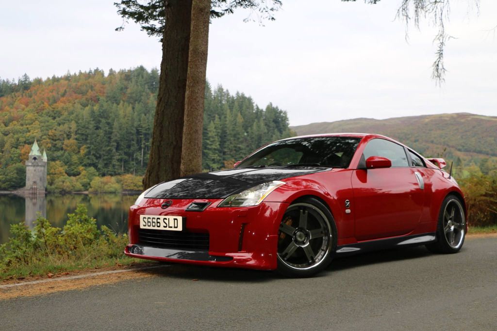
could someone be a lamb and photoshop my hood (and eyelids), to gloss black please
(I am tempted to do the grill and bumper add on at the bottom black aswell, but wondering if that's a little too much?Thanks
Nice pic
Sure, here's some options. I tried the lip with 2 tone (red & black) as well, but I'm not familiar with that lip, so wasn't entirely sure if what I did was correct.
Anyway, hopefully these help!
Just hood & eyelids
Hood, eyelids and grill

Hood, eyelids, grill and lip (Personally, I'm not fan of painting entire lip)
Hood, eyelids, grill, lip and sideskirt

Hood, eyelids, grill and part of lip (guesswork)

Hood, eyelids, grill, part of lip and sideskirt
-
Phew... nearly there in terms of catch up. I'm so bad at writing so it's been a bit of a struggle!
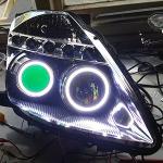
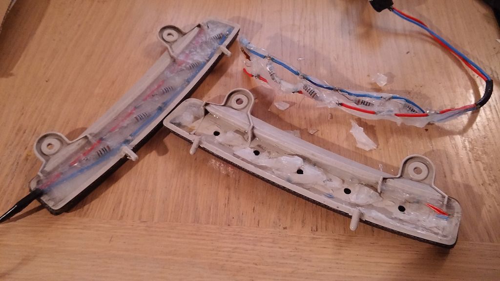
A few months after installing my DIY DRL, the LEDs started failing, as you can see below (it's meant to have 5 LEDs on each side):
I believe the failure was due to the fact I didn't know that the battery voltage fluctuates, and used resistors that have too low a resistance.
Anyhow, a week ago I finally removed the reflectors. By this time, it was down to 1/5 on one side, and 2/5 on the other. I even managed to take it off without anyone's else! Definitely learning, so proud of myself
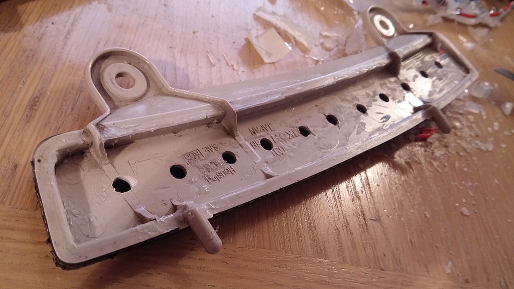
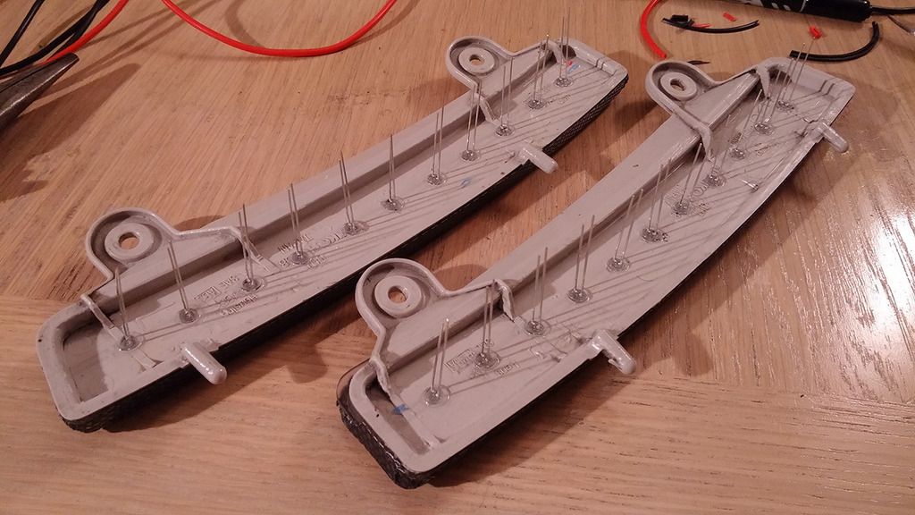
Here's what the reflectors looked like after removal.
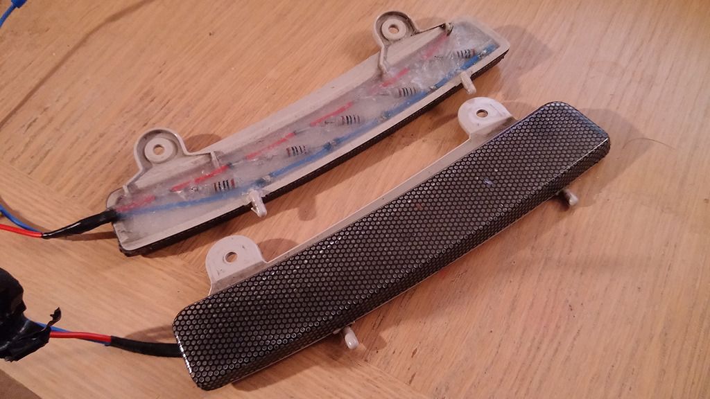
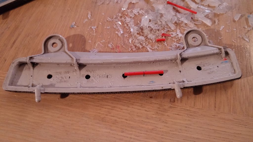
I started by cutting away the silicon and old components. I noticed that there was a little bit of water getting in where the wires came out of the reflectors. Makes sense really, as the silicon hadn't completely sealed this off.
My vision for "version 2" of the DRL was to try and get the entire reflector to glow evenly so I bought some wide-angle LEDs. I also decided to add more of them, as I thought it wouldn't be as bright as the previous LEDs. I increased the number of LEDs per bumper from 5 to 11.
I therefore had to mark where the other 6 LEDs would go. I didn't have a ruler I could curve, so I decided to use a piece of wire. Very "accurate"
With the half-way points marked up, I then used another piece of wire to try and keep it equidistant from the front edge of the reflector:
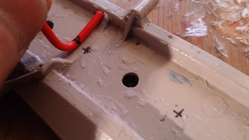
Which then allowed me to drill the pilot holes:
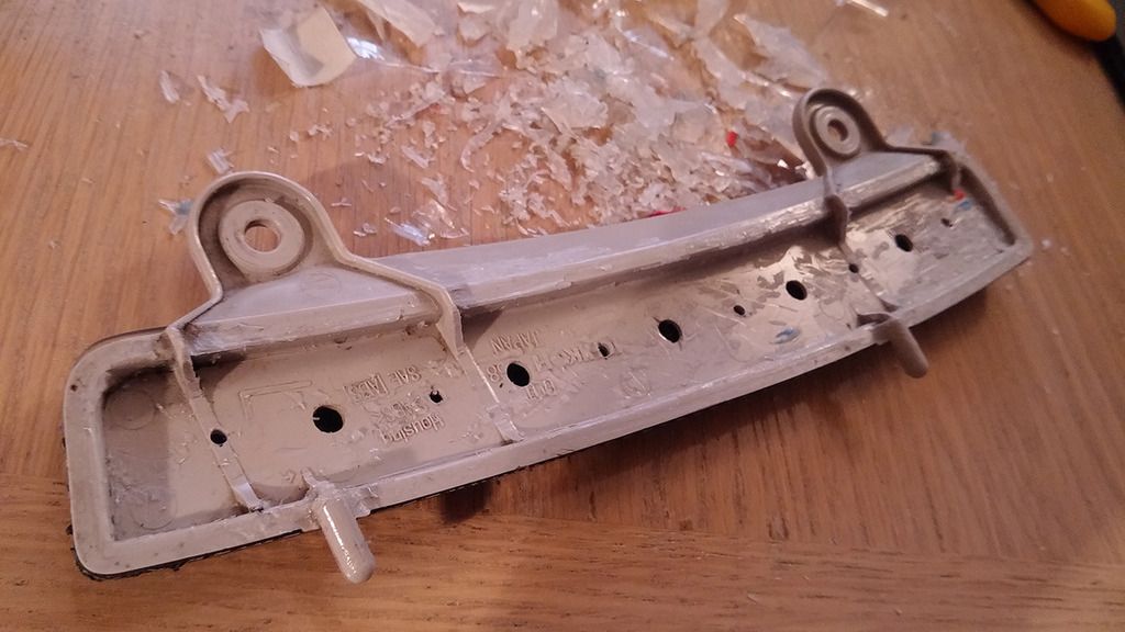
Which in turn allowed me to drill the 5mm holes. Beware, the plastic is very soft so you need to be really careful:
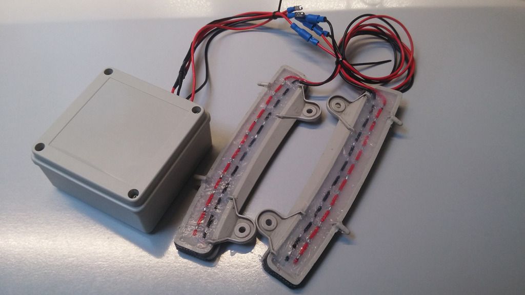
Next up, I sorted the power supply. I know there's a lot of electrically minded people on here (cs2000, flyboy etc...) so they'll probably tell me otherwise
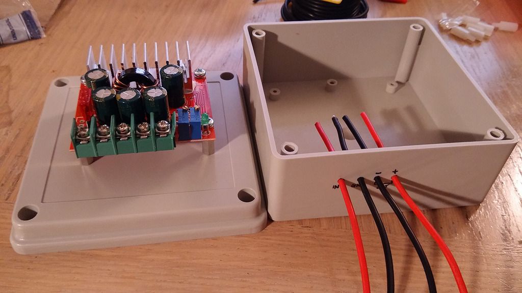
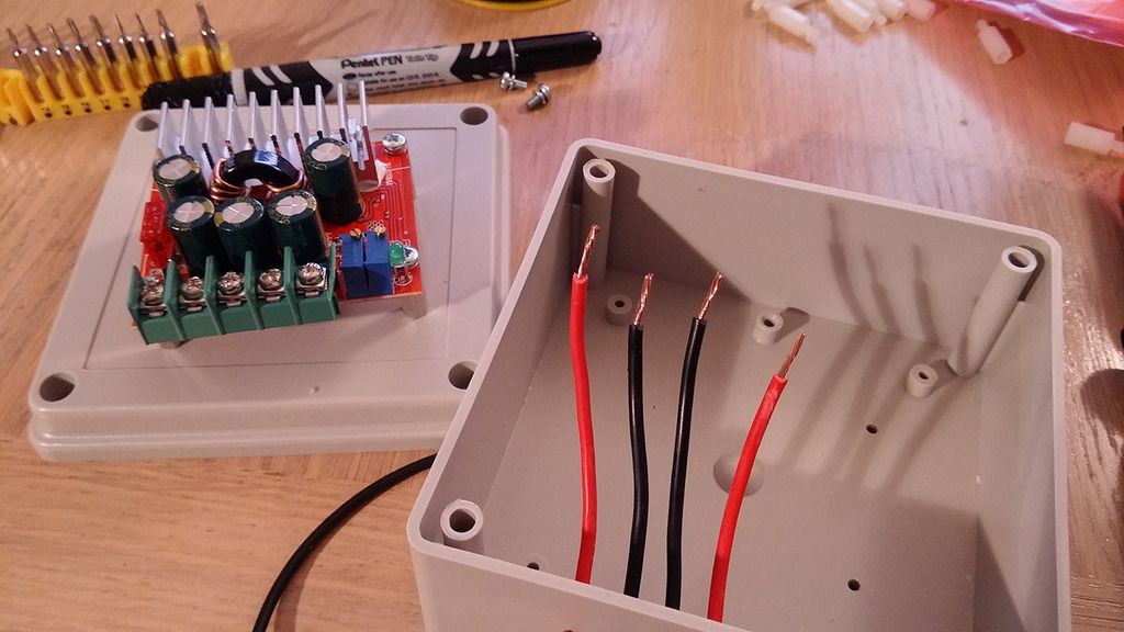
but after some research, I found that you can use a DC/DC converter to stabilise the voltage / current. I found one on Amazon that looked ok, at least to me (everything I know is from researching, so don't hold me to it!). Here's a link in case anyone's interested.So I got one of those, some spacers/screws and a waterproof case to put it in.
I firstly drilled some holes for the wires, and marked what they are with permanent ink:
I then used a piece of paper to mark up the distance between the screws:
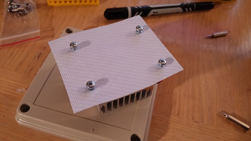
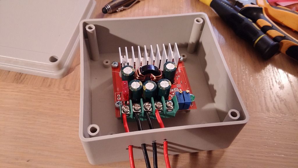
Then placed the paper on the back of the box with the DC/DC converter on top. I aligned the paper with the DC/DC converter, and then aligned the DC/DC converter so it sat roughly in the middle of the box in line with the wires (the below picture is before I aligned it). Once I was happy, I taped down the piece of paper and drilled the 4 holes:
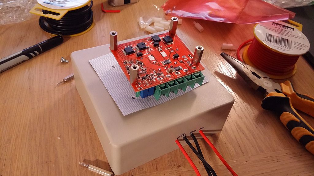
Now that the holes were drilled, I stripped the wires:
And secured them to the converter. I also screwed the converter to the box:
Now back to the reflectors. I had read that using sandpaper on the LEDs can help it diffuse, so I decided to give that a go:
Then stuck them into the reflectors. I used a bit of super glue to stop them from falling out, as some of them were a bit loose:
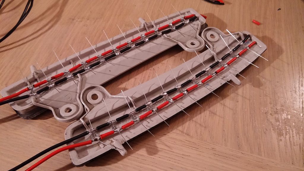
I then prepared the reflector wires:
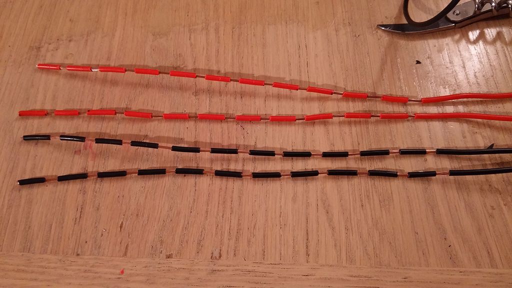
And stuck the LEDs through them:
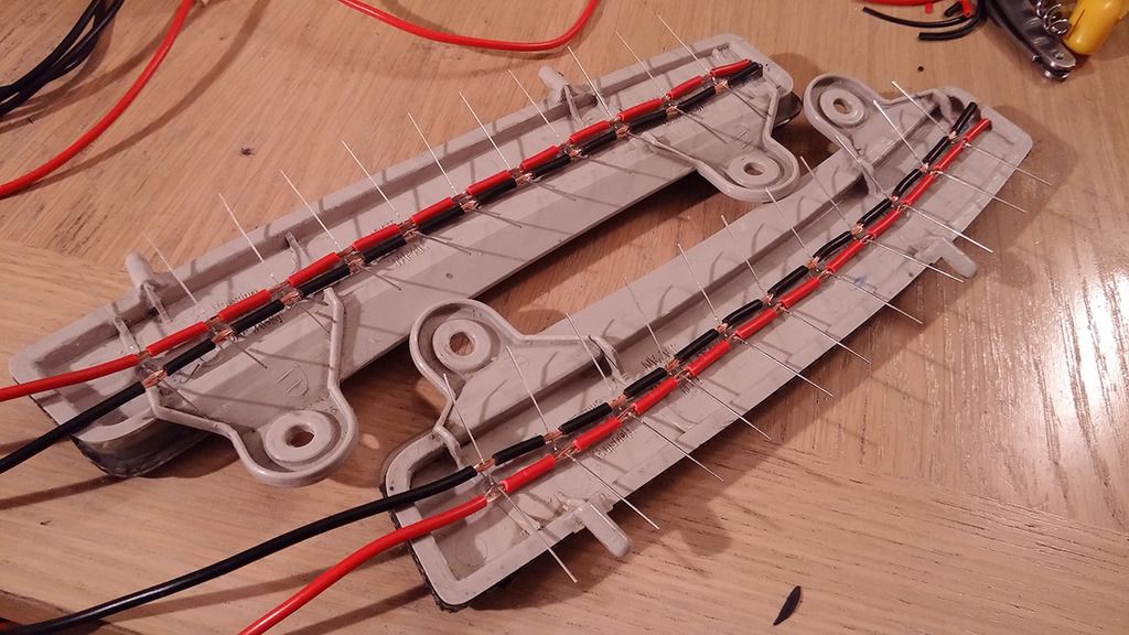
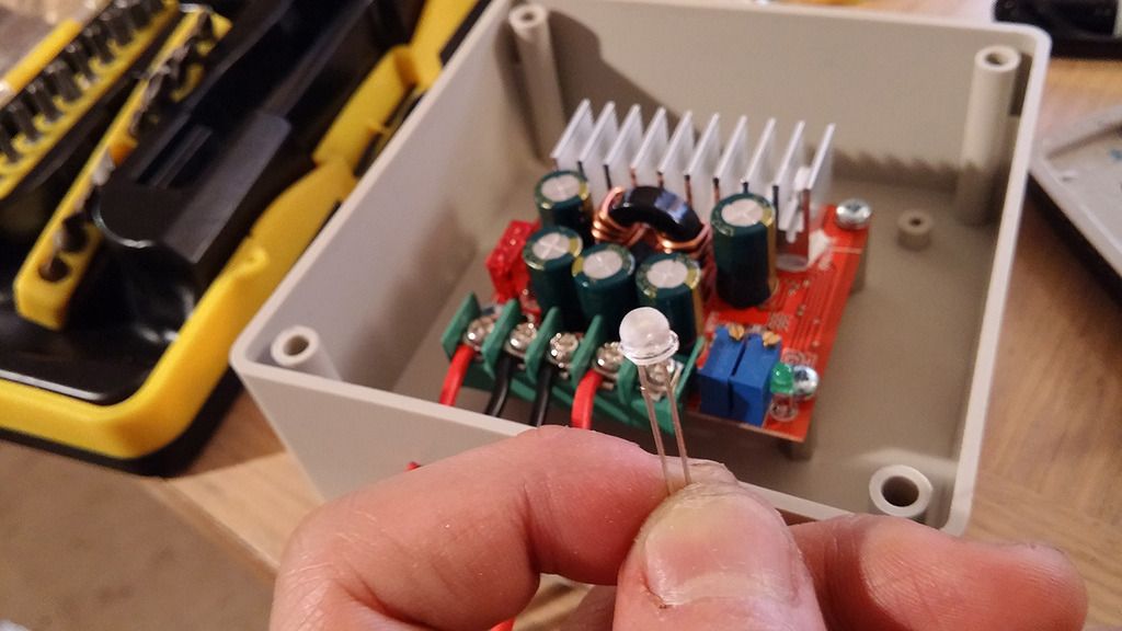
A bit of soldering later, it was all connected together. You may have noticed I didn't add resistors this time, which is because I could set the current output from the DC/DC converter. In the specs it said the optimum current for each LED was 20mA. As there's 22 of them in parallel, I needed a total of 440mA from the converter. It's my understanding (please correct me if I'm wrong!) that as long as I don't have more than 440mA coming from the converter, I wouldn't need any resistors.
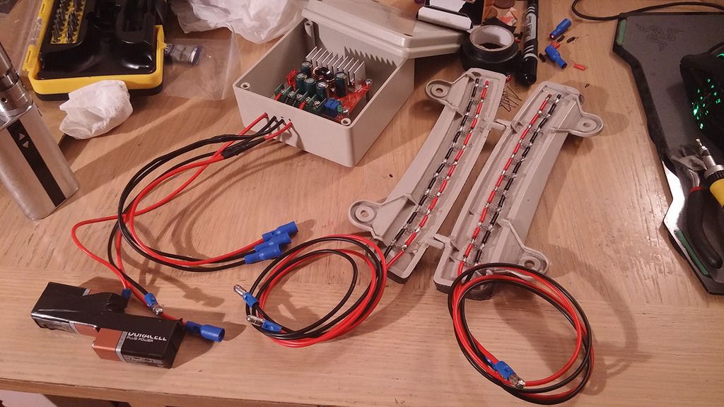
Bullet connectors were fitted to all the wires, and I tested it using 2x 9v batteries in series. The voltage and currents were set on the converter using a multimeter. I decided to set the current slightly lower than the 440mA I mentioned above, just to be on the safe side. I believe in the end, I set it to around 380mA.
Here's what I ended up with, prior to covering it with silicon:
The day after once the silicon had been added / dried:
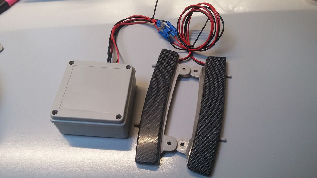
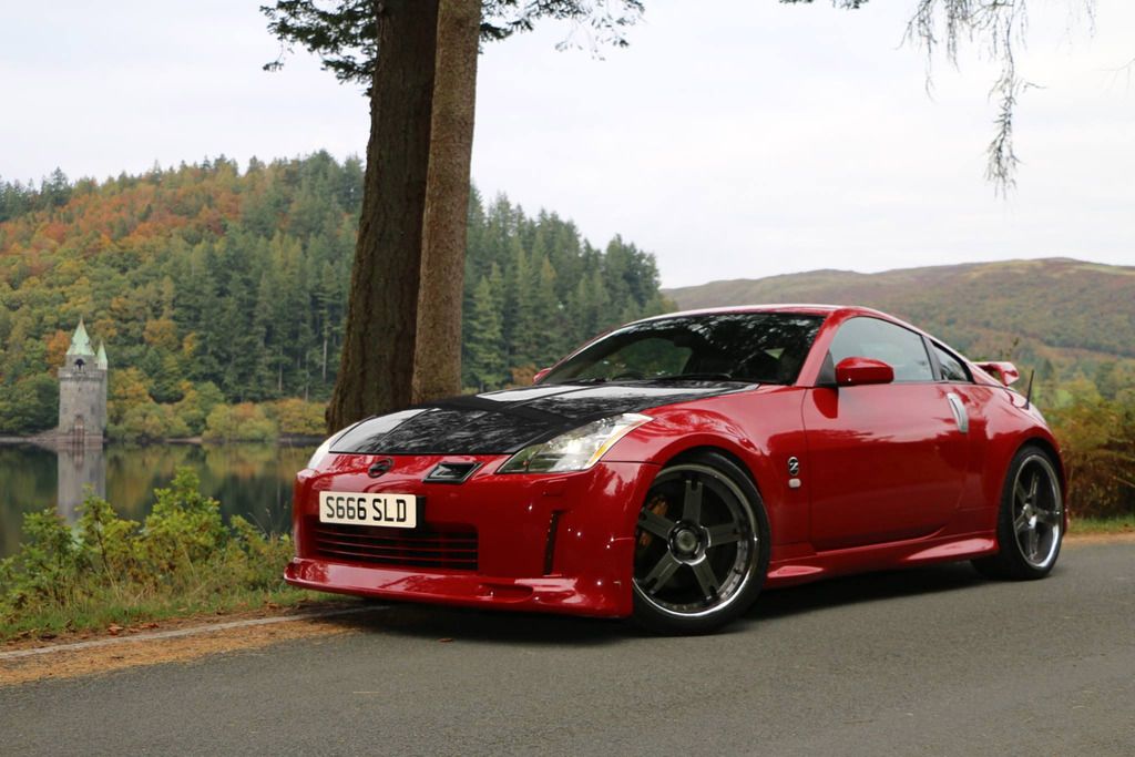
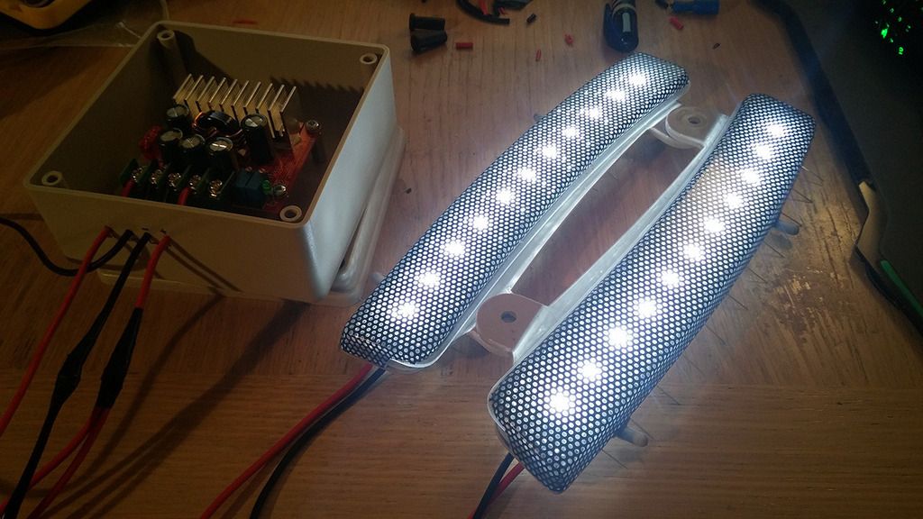
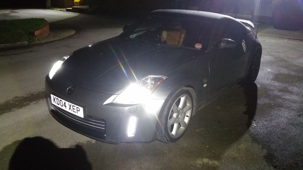
Annnd finally fitted them back in. Here's a shot of the sidelights + reflectors on (headlights off):
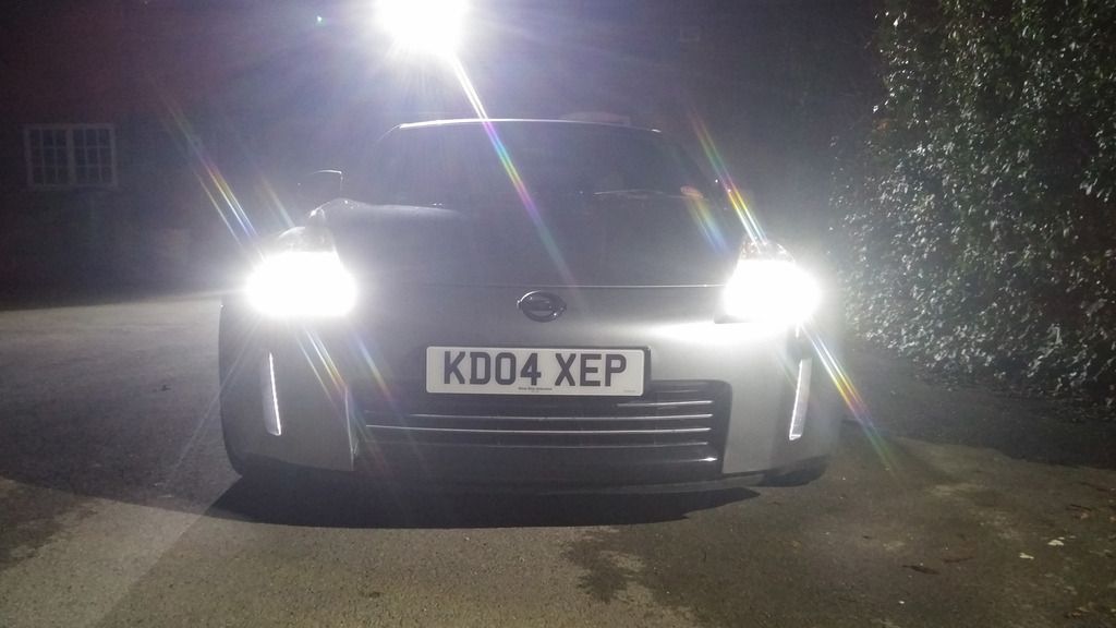
I have no idea of how correct my thought process behind the circuitry is. Hopefully it'll last this time, but if not, no biggie. For now, I'm glad I have a full set of LEDs.
-
 1
1
-
-
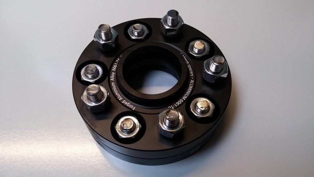
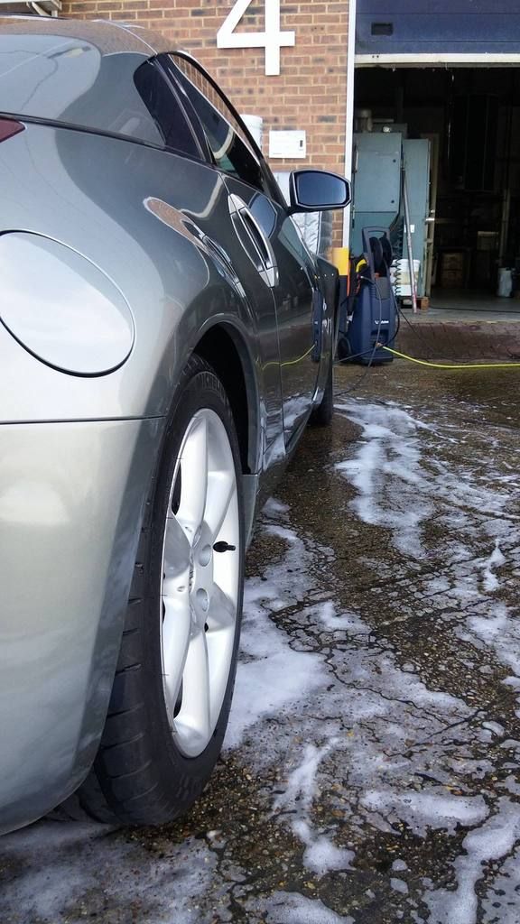
During my daily exploration of the forums, I noticed that GeorgeW was selling a pair of 25mm Torqen S spacers, which I managed to get for £55 delivered. These had only been test fitted, so were pretty much brand new:
I contacted Adrian@Torqen and ordered myself a pair of 20mm for the front as well.
Never having taken the wheels off myself, these sat in my boot for some time.
A little while later, Tuck posted about a group buy for rear LED indicator/fog/indicator lights. I loved the look of these, so contacted Car Lab to get myself a smoked pair for £103 delivered.
About 2 weeks later (well within their delivery estimate) these arrived:
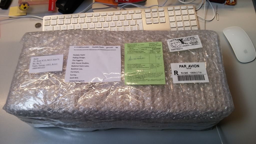
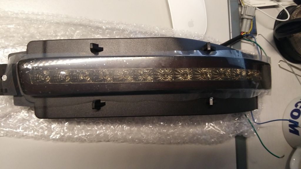
The quality looked good! Annnnd again, into my boot they went.
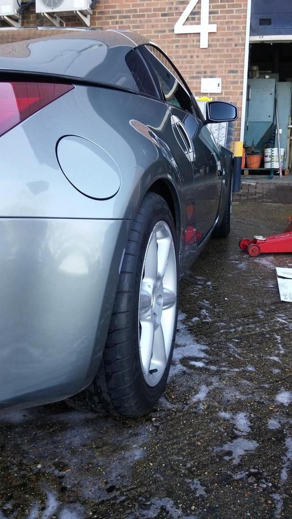
Once again, I had to enlist my friend to help out! After washing the car, he started by fitting the spacers:
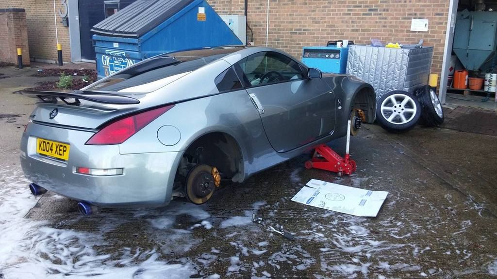
Before
After
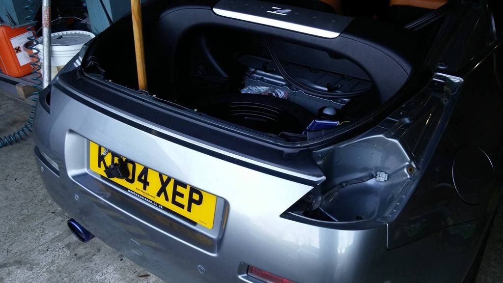
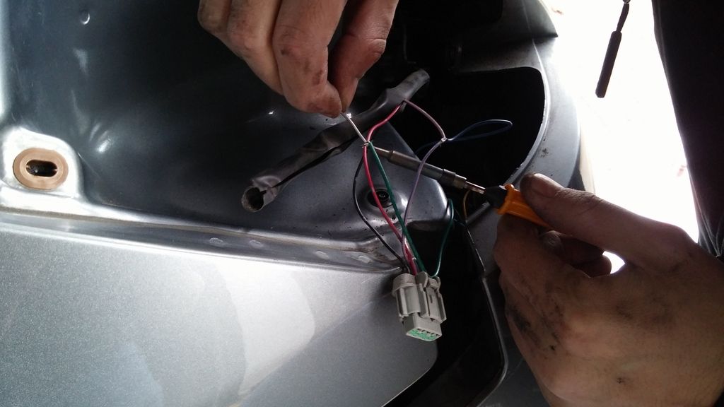
And then started work on fitting the LED lights, using a wooden pole to support the tailgate as my struts are a bit weak (one thing I plan to replace in the near future).
Soldering in some wires for the running/brake lights
Comparison shot
While we were at it, we also carried out a bumper tuck
We also tinted the brake lights very slightly. I don't have the LED brake lights yet, so didn't want to go too dark for safety reasons.
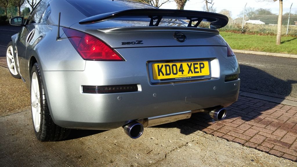
Before/after comparison (tinted brake lights, LED reverse/indicator/fog lights & bumper tuck)
Lights functionality
Another close up (taken a couple of weeks later, when I washed it)
It was a pretty productive day!

Notes:
-
LED light fitting guide
-
Bumper tuck guide - Very easy to do, but definitely helpful to have a second pair of hands. I've heard that some people have an alternative approach using cable ties as well
-
Fog light - The way I wired it above has running / brake lights. This means that I currently don't have fog lights. I will be rectifying this shortly, but tapping the brighter red to fog lights rather than the brake light. Another suggestion is to use diodes to combine that light for brake / fog lights, but apparently technically that's not legal. Worth taking a look and deciding what you personally want to do.
-
LED light leak - A short while after I installed the LED lights, it rained a lot and I noticed that the passenger side light was filling with water. It still works, but it's obviously not ideal. As Car Lab is based in Taiwan, I expected a troublesome process of getting it sorted. However after a few emails back and forth, they agreed to send me a replacement unit. It was all sorted in a few days, and they were extremely helpful. Only tiny annoyance is I have to wait the 2-3 weeks for it to be delivered, but that can't really be helped.
-
1
-
LED light fitting guide
-
Nice write up Hodaka. But, why has it taken you so long? í ½í¸„
Thanks!
And one word... laziness!
-
Keeping with my colour scheme, the next thing I wanted to do was darken the wing mirrors. I tried wrapping the wing mirrors in gloss black 4 times, and failed every time due to inexperience, heat gun and a helping hand (it's really awkward to try and do by yourself!!). Mainly due to my ineptitude though...
Here's what my last attempt looked like (I had given up by this point, hence the left over vinyl):
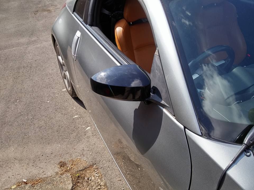
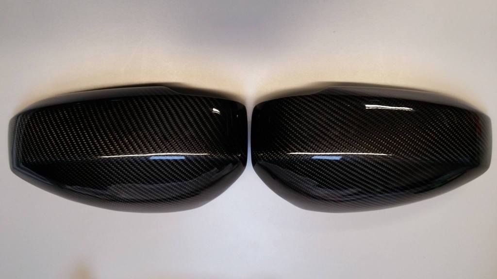
I was really liking the look. I got a quote from my garage, but as their estimate was £250, I decided to go for Tarmac's CF mirror / B-pillar covers instead.
And here it is fitted:
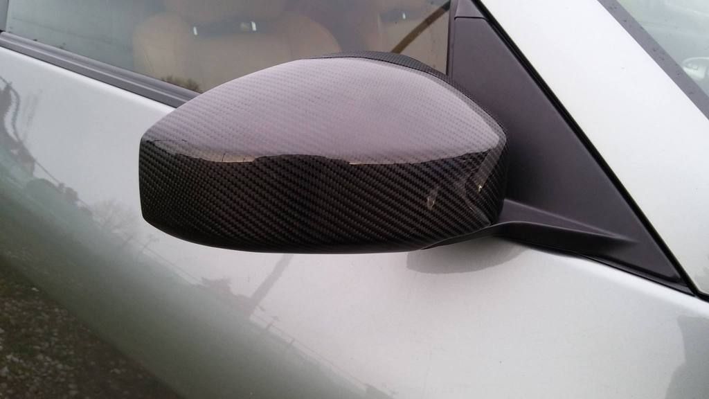
Pretty happy with the results!
Now I'm just waiting for the B-pillars to arrive. Notes to anyone doing this, from Tarmac:
These mirror covers fit over existing OEM mirror housing for a great look, 3M tape is fitted, a 3M promoter must be used to ensure a good stick, area must be degreased and dry, we also recommend silicon or super glue for extra security. Failure to do so may result in the mirror covers not staying stuck in place.I washed the wing mirrors, wiped it with IPA and used silicon to stick it on.
-
1
-
-
Short one with a few bits & bobs.
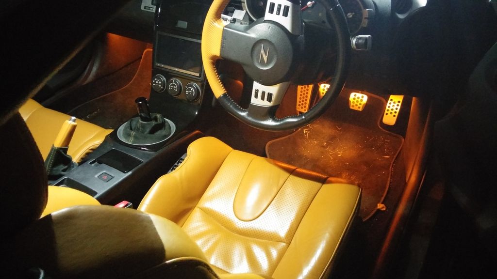
I managed to find some replacement amber LED strips for the footwell lights, so I put those in. Not sure about this either, but it'll do for now
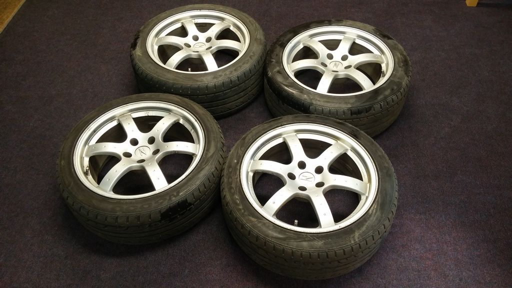
And found some rays on eBay for £150! Bargain!! A little kerbing & some bubbling, but I can't complain:
As my exhaust tips and strut brace are blue, I decided that the colour scheme of the car would be gun metal / black / blue. So I requested Chris@Tarmac for his best blue nuts:
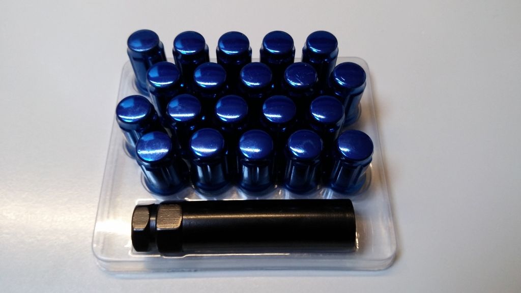
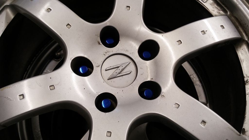
I want to try refurbing the alloys myself (failing that I'll get a pro to do it) before putting them on the car, but here's a little test fit of the nuts in the alloys. Liking the look:
Annnd got some free eyebrows from Zeezeebaba, who lives nearby. Although I haven't fitted these yet either due to an issue with the headlight position (it's leaving too little room for the brows to fit nicely), here's a test fit:
Lots to look forward to!
-
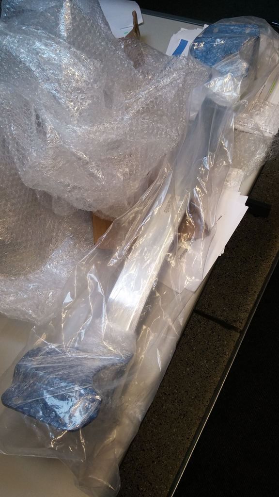
Engine dressing is quite low on my list of things to do tbh due to financial restraints, but I when I saw Bullet selling some left over front strut braces from a group buy, I couldn't resist. Apparently his wife was fed up with them sitting around the house, so he was selling them for £67.99.
It was delivered a short while later. Was very well packaged too
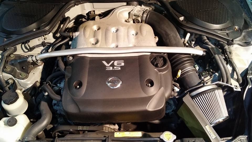
This was something I was unsure about, so I got my friend to install it for me
Before
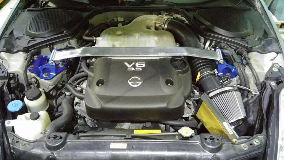
After
-
This one's a quick one (and actually happened before my footwell light installation), but my car didn't come with floor mats. Something little, but it really bothered me!
Luckily, I noticed Ian was selling his old ones so I nabbed them! So glad I now have mats!
Notes for anyone buying mats - I didn't know this for ages but there's a little plastic peg under the drivers side seat that you can attach your mat onto.
-
Cool build, you've been busy
Thanks! Yeah, I'm new to modding but am loving it
-
1
-
-
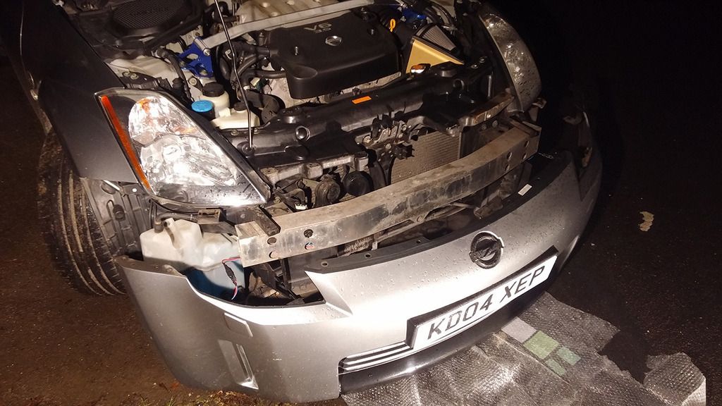
I'd been aware for a while that my clutch was worn. The biting point was super high and this was confirmed by West Way Nissan (where I bought it from. I dislike them now, but that's another story) as well as the garage I now use (TGM Sport in Fleet). TGM said that it'll need replacing in the near future, but for now it should be ok.
I decided I'd start looking for when I needed to replace the clutch. Again, the impulses kicked in and I decided to just go for it. A quick PM to Ewan@CMS and a few days later, the Xtreme Organic Clutch & SMF arrived:
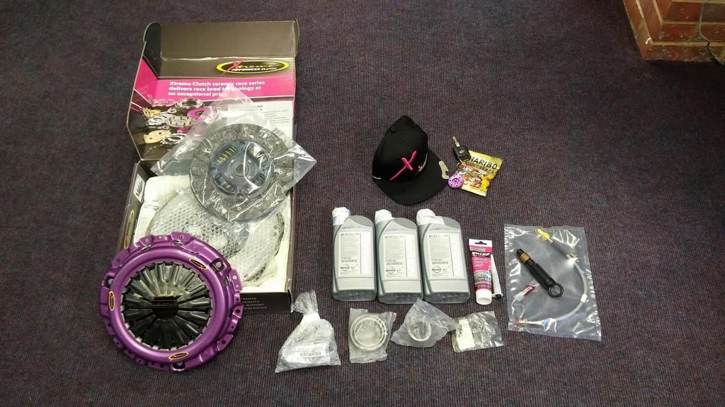
What can I say... I'm super weak to pretty things.

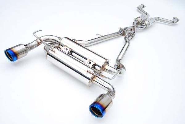
Speaking of pretty, I always wanted an Invidia Gemini. So I dropped Adrian@Torqen a PM, and less than a week later that had arrived as well. I got it delivered straight to the garage so I don't have a pic, and I'm sure you're all aware of what it looks like, but here it is again:
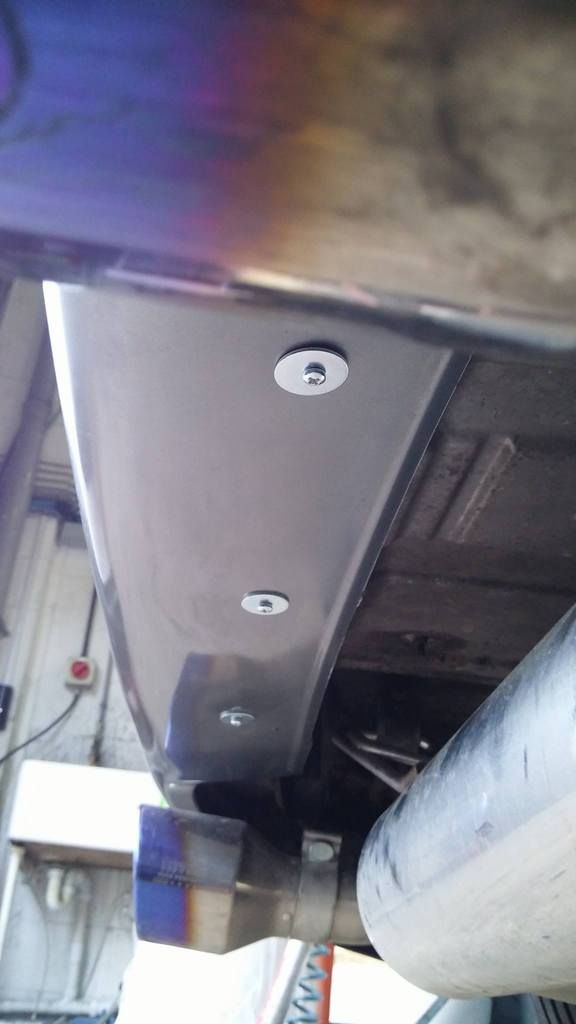
This was then all fitted:
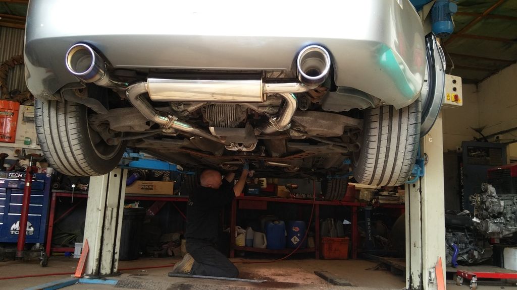
First time I've seen the underside of my car.

As soon as I started the car... wow... such a difference in exhaust note. And the clutch... All I can say is that I was over the moon
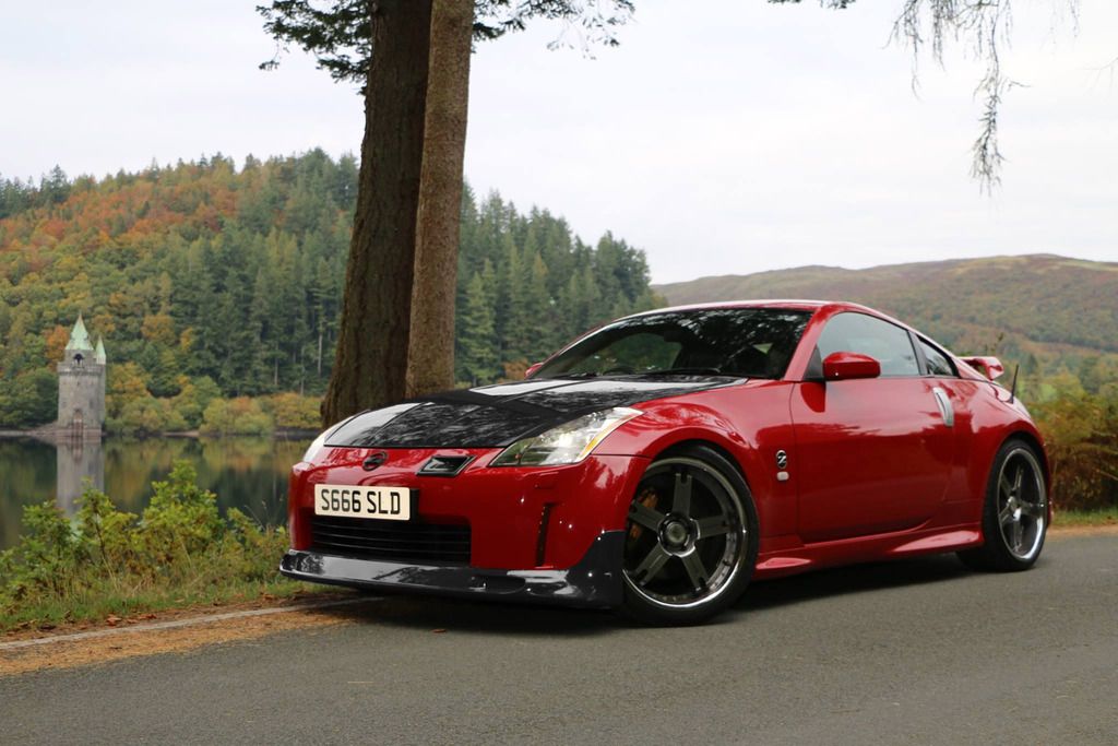
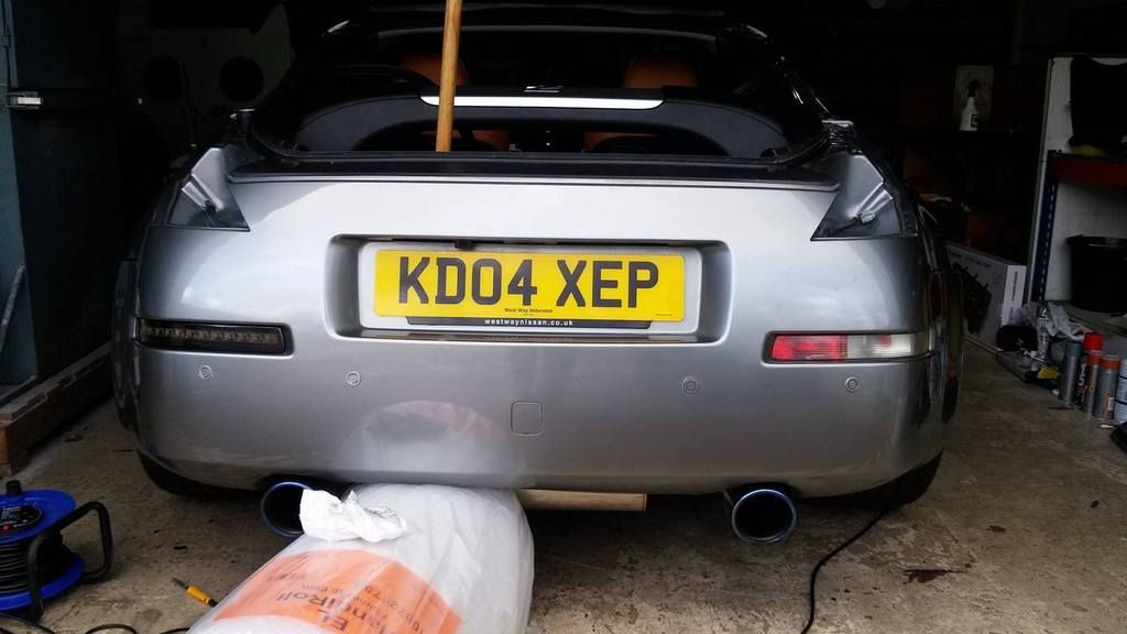
Although I took this recently (so it shows other stuff), this is what the exhaust looks like fitted:
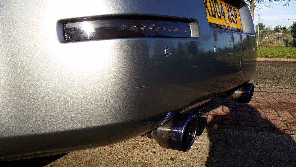
And of course, the obligatory video:
Revs showing the SMF
Sound of the exhaust (should have taken it in landscape...)
-
1
-
-
Great write up Hodaka, really enjoyed reading that.
Thanks Zeus!
-
One day during my daily internet / forum crawl, I came across a thread where someone had installed some DIY footwell lights. It went on about pulling the dome light out, taking the cover off the A-pillar etc... These were all things I've never done before, but I was pretty intent on doing it so I carried on researching.
I found a few articles I thought were useful so took note of those. These included:
-
Info on the entire process
-
A useful pic of how to solder the wires - I soldered it a bit differently, but this was what gave me the insight into how to do it
-
Some useful Q&A
-
BCM related info 1
-
BCM related info 2
First thing I did was to buy the LED light strips.
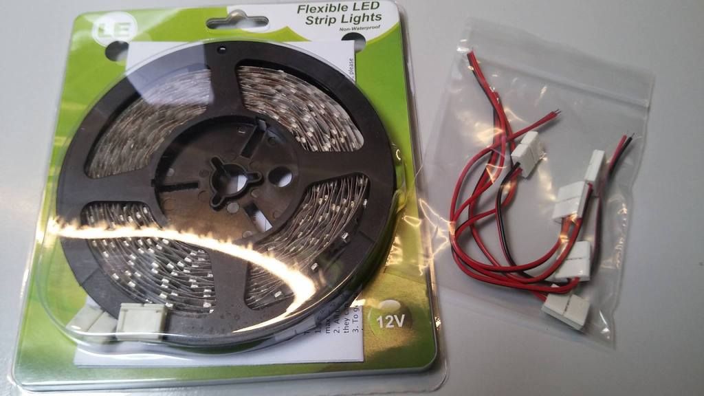
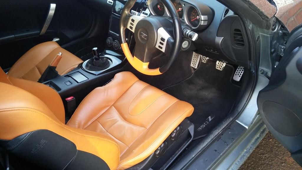
As you have probably seen from my previous posts, I have the orange seats (I forget the name... wasn't it named after a breed of horse?). I therefore wanted to get some amber lights, but couldn't find any that were reasonably priced. I therefore settled for red as a starting point. I planned to set it up so that I can replace the strip easily if I liked them. FYI I bought it from a company called Lighting Ever. Good service and the product seemed to be of good quality.
I did originally plan to use a relay as that seems to be the safer method, but decided against it in the end partly due to laziness and partly as I wasn't confident in wiring a relay in. It's worth noting that I have replaced all the interior lights with LEDs as well.
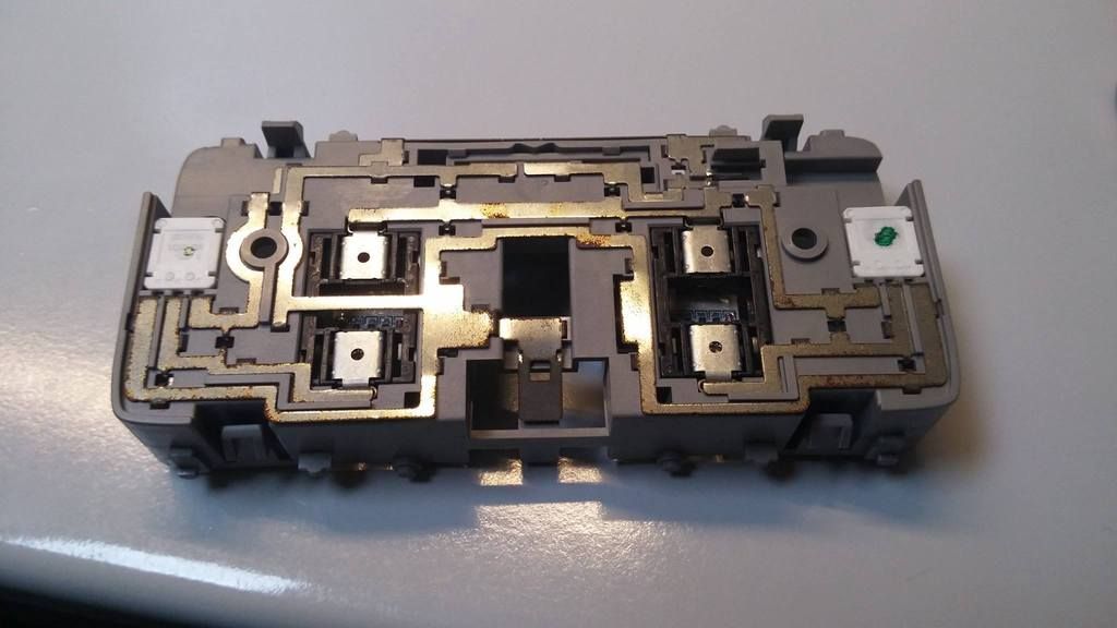
First things first, I disconnected the battery (wound down the windows first) and took out the dome light housing:
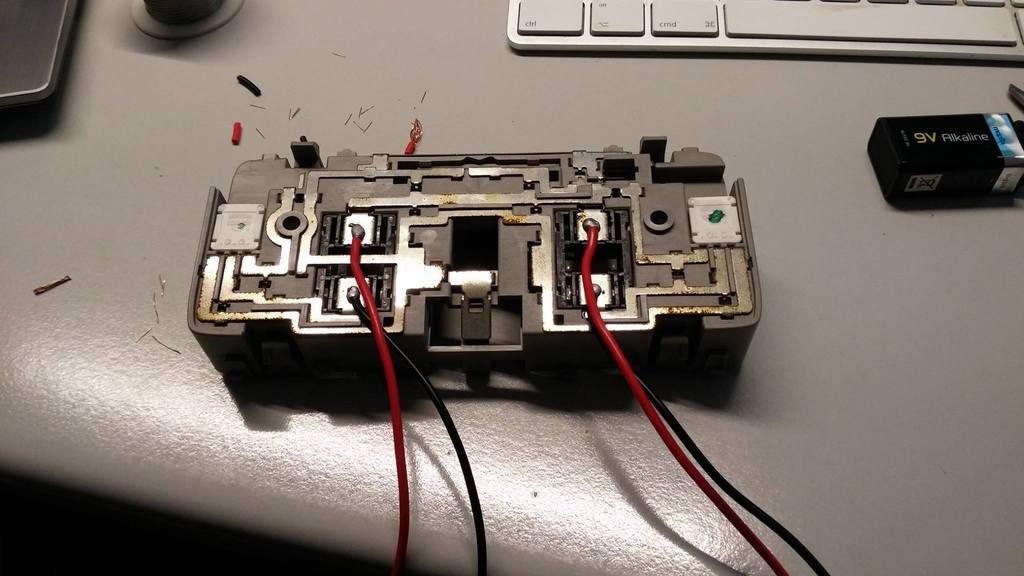
I then soldered 2 sets of wires to the housing. This is so that each footwell light can be operated independently from each other. As you can see, I did it to the connectors to the bulbs themselves, rather than where the guy in the 2nd thread (in the list above) did. It's exactly the same part of the circuit, just physically it's a different location. I liked the idea of soldering it onto here as there's convenient holes you can stick the wires through
Each wire was several meters long as it had to go from the dome lights, across the head liner, down the A-pillar and into each footwell. I personally went down the driver's side, so the wires for the passenger side was a bit longer. I then taped it together using electrical tape every 10cm or so, just so it's tidy. Although I'm still bad at these things, I do like to try and keep things tidy to the best of my abilities.
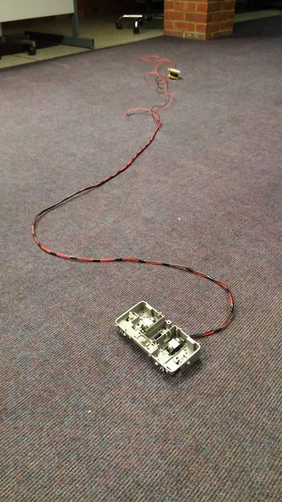
Feeding this wire through the head liner was an absolute PITA as I didn't have much in terms of tools as I was at the office. So what I ended up doing was feed some thicker wire (17A) with a loop at the end through the head liner. After a lot of struggling I managed to see the end of the wire near the top of the A-pillar. It was a bit too far for my fingers to reach, so I made this using a paper clip
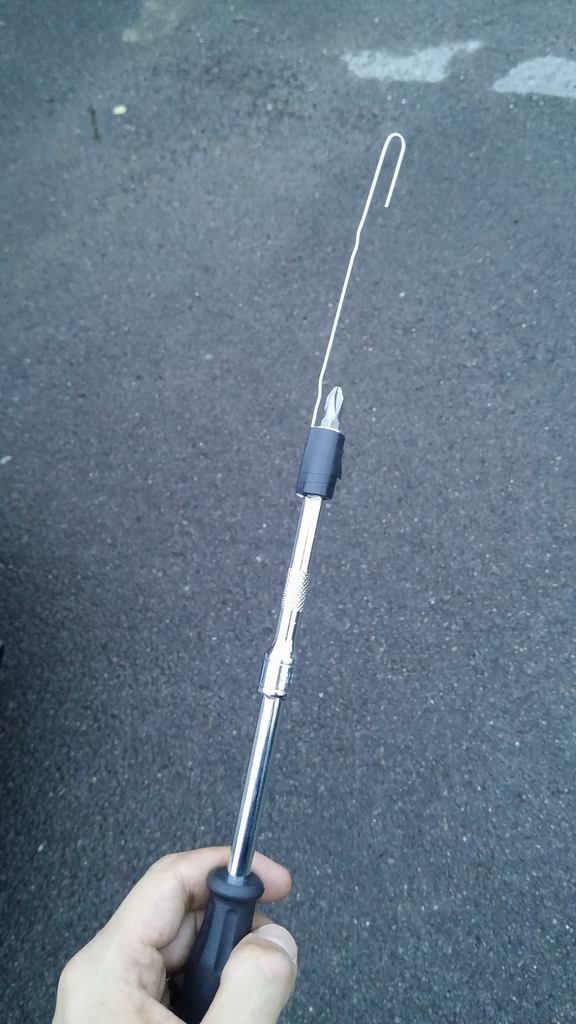
Carefully wiggling it around, I managed to hook it onto the 17A wire and pull it through:
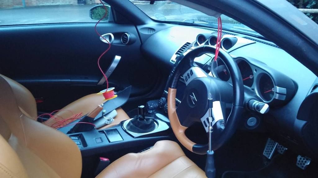
I then taped dome light wires to the 17A wire, and pulled it through from the dome light housing area to the A-pillar:
I then ran it down the A-pillar and cable tied it to keep it tidy. I had no idea what the other wires were for (dome light power + side air bags?) so was very careful not to disturb anything.
From the bottom of the A-pillar, I fed it straight down to the footwells.
My plan for the night was to just sort out the driver's side, as feeding the wires through to the passenger side would require me to pull out the centre console. It was getting late and this definitely wasn't something I was up for, especially as the wife was getting a bit annoyed by this stage!
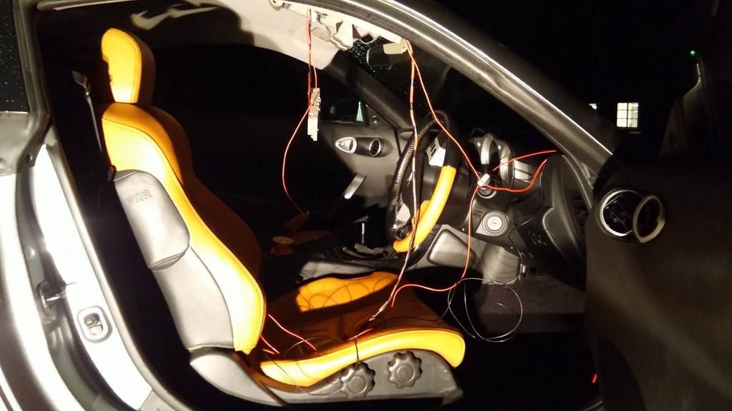
I stripped the end of the driver's side wires and crimped some male bullet connectors. I then cut some of the LED strip, put on the connector thing (shown to the right of the LED strip above) and crimped the female connectors to that. After I connected it all up, the driver's side was lighting up as planned.
Next I had to attach it somewhere to the top of the footwell. I peeled back the double-sided tape on the rear of the LED strip and tried to find a suitable place annnnnnd... somehow managed to short the circuit!
Having read about blowing the BCM, this is where I sh*t myself. Luckily I replaced the fuse and all was well. Not wanting to do any further damage, I decided to call it a day. I taped up the remaining connectors to insulate them from one another, and stuck the LED strip to the side of the seat just to keep it out the way until I thought of a better solution.
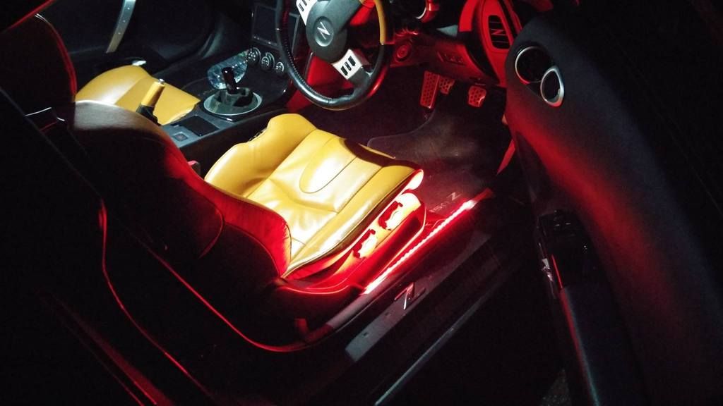
Mmmmm... try hard boy racer red.
Anyhow the LED strip stayed there for quite a while. I felt a bit self-conscious each time I got out the car at night
So it was time to research again! I found some housing specifically made for housing LED strips, but they seemed to be made of aluminium. Considering I wanted it purely for insulting the strip, it deemed it unsuitable. After a bit more brainstorming, I decided that I could try using some PVC (?) tubing they use to aerate aquariums. I checked the width of the LEDs (which turned out to be 8mm) and ordered some PVC tubing from eBay. I think I got the 8mm/10mm (inner/outer diameter).
After the tubing arrived, I squashed them slightly to make them oval and inserted the LED strips. I then taped it up best I could to insulate any exposed parts:
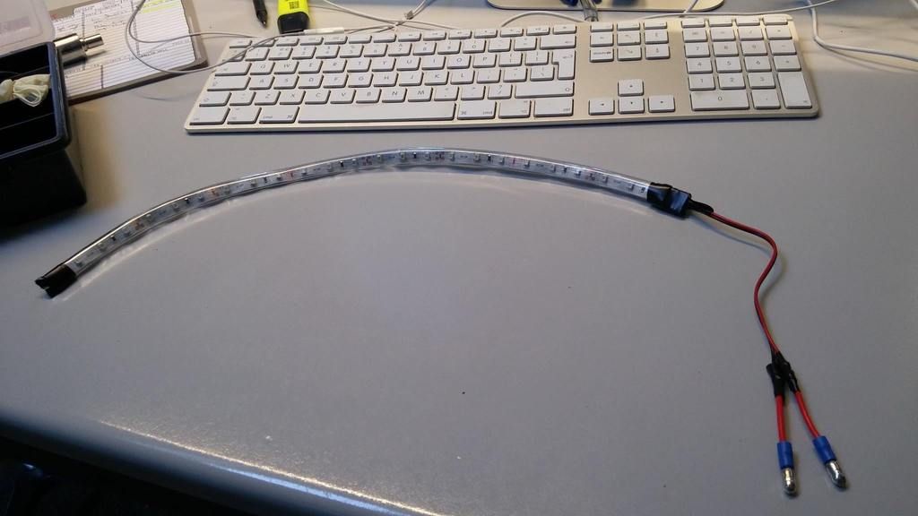
Pretty good solution for £3!

Now that I could be confident it was properly insulated, I just cable tied them to what I could:
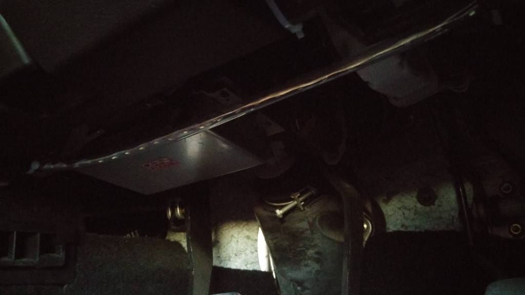
I then fed the passenger side cable from the driver's side footwell, into the centre console and through to the passenger side. I then just repeated the rest of the process to finish it off:
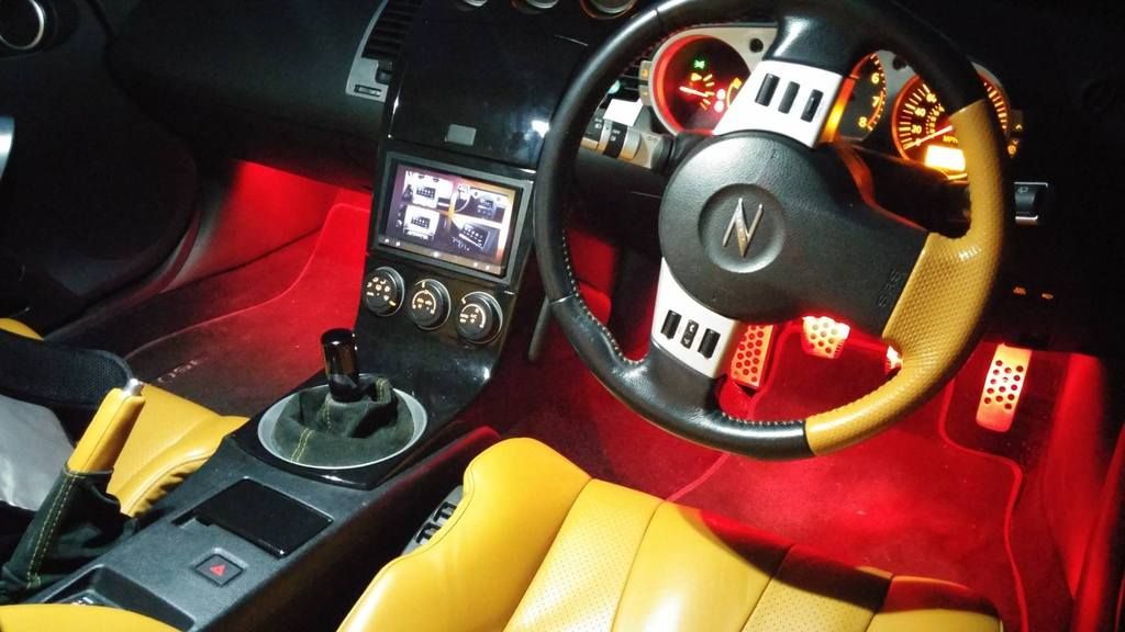
As I say, I wasn't a fan of red, but was super pleased with the results.
Notes
-
Female/male connectors - I'm sure this is something which is obvious to anyone who's done any DIY electronics, but after doing these projects I came to the conclusion that it's best to use the female connectors to the "live" side of the circuitry. This will help prevent unintentional shorts as the metal isn't sticking out. So in this project, stick the male connectors on the LED strips, and the female connectors to the wires from the dome light.
-
BCM - Make sure you read the stuff about the BCM and understand the risks you take by doing this project.
-
Info on the entire process
-
great work and lovely feeling being able to do stuff yourself!! dash looks MEGA now too.
any pics of the exhaust?
david
Yeah definitely do enjoy the DIY process
Yep, I'll upload those shortly. I plan to right a few more updates tonight!
-
Thats great mate, thank you for doing that! Clearly made up my mind now on what colour to go for.

No problem, happy to help!
Just out of curiosity, which colour are you going for?
-
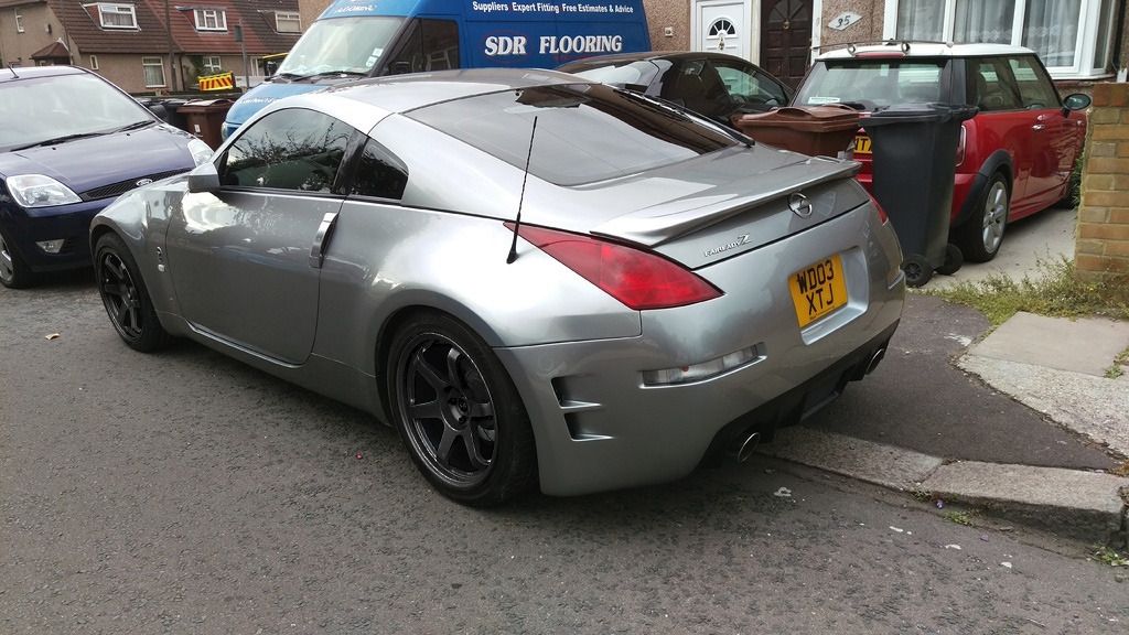
Can someone get a close up photo of smoked fitted?
This close up enough for you?
Ignore the bird poo that's etched into my bumper just below the number plate. Was the (lack of) work of the previous owner

-
1
-
-
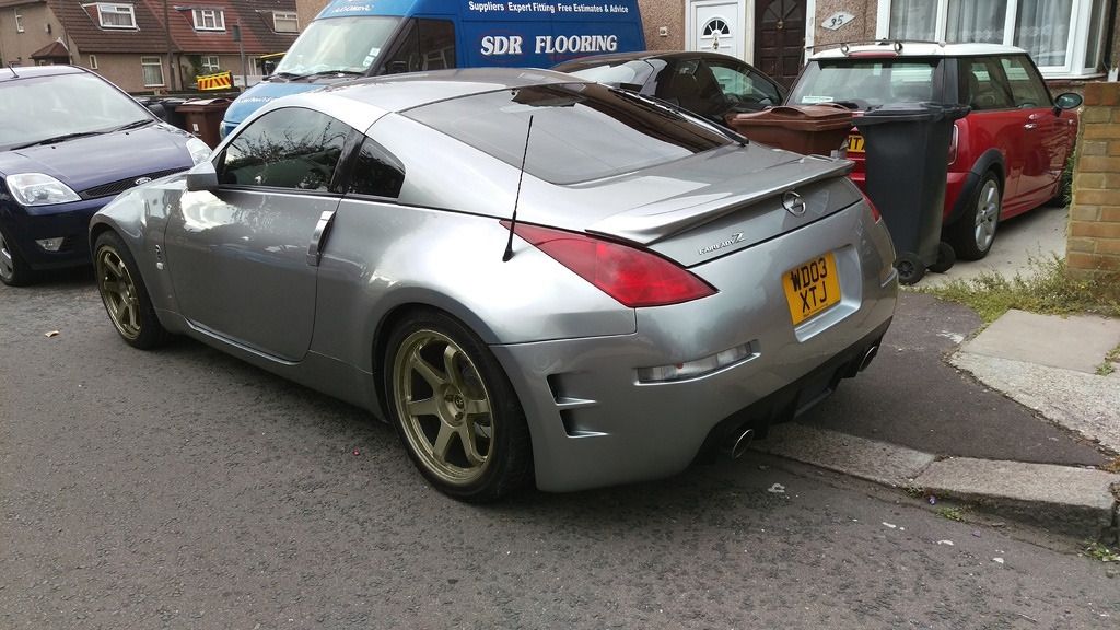
Hi Hodaka,
As requested I have put the pictures of my car and the wheels below. The rota grid drifts are the ideal choice but would like to see how they look in matt bronze and matt black. Also interested in the Rota PWRs but they only come in silver with only one off set. Pictures of the alloys are below.
Thank you mate, really appreciate it.
Hey,
So... other than the fact I used the fronts on the rears as well (made my life a bit easier), do these help visualise it?
Let me know if you want the colours tweaked!
-
1
-


Rear bumper Led indicator/fog/ reversing light by carlab
in Group Buys
Posted
Just a quick one, the replacement unit came today. It was extremely well packaged - the unit was in a bubble wrap bag, which was then rolled in more bubble wrap, and finally surrounded with layers and layers of some foamy padding. I have no idea how they managed to fit it all in the box.
Will report back in once I've had a chance to fit the unit. I'm in the process of moving into my first house right now, so pretty busy!!