

AFTERSHOX
-
Posts
124 -
Joined
-
Last visited
Content Type
Profiles
Forums
Events
Gallery
Store
Posts posted by AFTERSHOX
-
-
 Some great ones here !
 Here is my contribution....
Tarmac Sportz: your modification mistress !
-
 - I might be joining the 370z club soon.....
Watch this space !
-
SECTION 6) RE-ASSEMBLY AND FINAL CONFIGURATION
So, here we are – the FINAL STAGE of the Process; and possibly the most difficult of all to write up as a guide;
(Use this section as a rough guide, but ultimately the placement of the HARNESS etc. will be very much up to you!);
If you decide to place the HARNESS outside of the Centre Console (as I did to improve AIR FLOW behind the HU!) – then you’ll likely need to modify the “Business Card Drawer†& bracket to accommodate the loss of space behind the drawer; In my opinion – the “drawer†was useless anyway – so losing the drawer (for storage) is no big deal; You still retain the “original dash†look – but it is only the drawer “front†that you see, it no longer functions as a drawer; the bracket is modified – and the mechanism is removed;
Connecting the HARNESS outside of the Centre Console (to make more room behind the HU for AIR FLOW)
For this, we’ll use the space in the top right corner of the Passenger Side Lower Dash!
You may find this easier to do if you remove the (Instrument Side Panel – LH) first; this is the padded knee panel on the Left Hand Side of the Centre Console; it is held in-place with just one screw (towards the rear) and a clip on the front.
Chop back plastic trunking and tape to pull the OEM (CAR) BOSE HARNESS outside of the Centre Console (AREA) into the passenger side under dash (AREA)
Split the Antenna cable away from the connector – (MAKE SURE it is long enough to reach the HU)
The antenna cable is quite ‘short’, but with some clever ‘unpicking’ – you can make the aerial connector reach the HU (with ease)
Connect the ICT HARNESS / ISO HARNESS
Connect the OEM HARNESS to the ICT+ISO HARNESS
The following cables need to be passed through the ‘gap’ into the centre console
 Antenna / Aerial
 Red / White / Yellow / Black – RCA connectors
 MAIN Earth wire
 ISO Connector
Connecting the HU
Loosely place the HU into the Centre Console
Earthing Points Check & Tighten
Make sure your 2 x EARTH (one for the ISO HARNESS, and one for the "Parking Brake Bypass") are connected and secure.

Route the BlueTooth Module out of the centre console via the Instrument Side Panel – LH (opening) into the Passenger Side Dash Lower (AREA)
Connect the AUDIO JACKS
o Red/White
o Yellow/Black
Connect the “Parking Brake Bypass†(EARTH / GROUND] wire
Connect the “MAIN EARTH / GROUND†wire
FINALLY - Connect the ISO Connector to the Head Unit

Connecting the Camera
Run the cables to Centre Console (via) the Passenger side Dash Lower (AREA) via the (Instrument Side Panel – LH) – NSM#IP-14
Crimp the correct connector to the “Reverse Sense†wire (this has a bare end currently)
Connect the Camera Video Cable (Yellow RCA) to the R-CAM socket on the HU
Connect the “Reverse Sense†wire to the HU
Connecting the BlueTooth Mic
Route the BT mic jack into the right hand side opening of the centre console and then back into the centre (directly behind the HU)
Plug the BlueTooth Mic into the MIC socket
Installing the HU in final position (ALL WIRING CONNECTED)
Once the HU is all connected up – manoeuvre the Head Unit into it’s FINAL POSITION

Now secure it (in place) using the screws – replacing the “Heater Controls Moduleâ€. The Centre Console will be re-assembled OVER the top of the unit once the Dash is back in place.
Re-Assemble Passenger Side Dash (PLUS modification of the Business Card Drawer) to make room for accommodating the HARNESS outside of the Centre Console.
In the picture below, you can see the modification I made to the Business Card Drawer BRACKET; It had to be cut back (retaining the locating posts and screws);
I also had to make a 'backing plate' to which we can FIX the front of the card drawer - for this, I used a piece of hardboard (cut and shaped to size) - it looks like a "dogs breakfast" from the back - but once the drawer is stuck on - it looks OK.
If you didn't want to re-attach the drawer front - you could probably use the space for a "mini speaker" (and connect the wires to the NAV harness) - this would give you VOICE NAVIGATION !
*tip courtesy of Dave!*


You'll also need to cut a HOLE into the 'backing plate' to allow the screw bolt to be "pass through" to re-assemble the passenger side dash and hold it back in-place securely; the photo below shows the 'access hole' and a couple of cutouts at the bottom for the drawer to sit "FLUSH" against the dash (when it is re-attached using STICKY PADS)

Re-Assemble the Centre Console
Head Unit & Heating Controls are re-attached; PLUS the (3 x DIALs at the top) re-connected; the console section is then held back in-place by the two screws at the bottom of the console plastics;

Now we put back the gear / shifter covers; and heating controls; REMEMBER to re-connect the HAZARD SWITCH and HEATER CONTROLS (the white flat cable) first

..and finally - we re-connect the NAV CONTROL BUTTONS. Remember to put the 2 x screws back-in before replacing the trim piece between the controls and the NAV SCREEN;

Put the CAR BACK TOGETHER
As per the guide – put the remainder of the car back together by replacing all removed panels and trim
Configure the HU audio (Pre-outs) REAR or SUBWOOFER?

Configure the Rear Camera

Test Reverse Camera

Test Steering Wheel Controls
(All steering wheel buttons should perform a function – except for the TELEPHONE button)
FINAL INSPECTION
Using double-sided tape or STICKY PADS; attach the “business card drawer (front)†to the dash panel

Admire your new system

FINAL (FINAL) CHECKS
As with anything electrical – it is always good practice to check that all systems are working again following any works; e.g. test your hazards / Indicators / Side Lights (also check that the HU illumination / dimmer works ok) / Full Lights etc. etc. plus test the heater controls as well.
++++++++++++++++++++++++++++++++++++++++++++++++++++++++++++++++++++++++++++++++++
IF YOU FIND THIS GUIDE USEFUL – PLEASE LET ME KNOW; LIKEWISE IF YOU FIND ANY OBVIOUS MISTAKES / ERRORS OR MISSING STEPS – FEEL FREE TO UPDATE THE THREAD WITH ANY EXTRA TIPS / POINTERS.
IF YOU FOUND THIS GUIDE INVALUABLE, THEN YOU MAY WISH TO CONSIDER MAKING A DONATION TO THE BOYS & GIRLS @ 350Z-UK.COM FOR RUNNING SUCH A GREAT WEBSITE & FORUM! WE WOULD BE LOST WITHOUT IT!
HARD WORK, DEDICATION, EDUCATION AND A PASSION FOR ALL THINGS ‘Z’ !
(AFTERSHOX from 350Z-UK.COM)
-End-
-
Thanks Neo (..for the sticky) and SpursMadDave ! .....but there is just ONE more section to come ! ..then I'm done !

Appreciate the feedback and comments for my efforts ! ..and if the guide helps just one person (..or stops them asking "where does that wire go>?") ..then job done!

SECTION 6) RE-ASSEMBLY AND FINAL CONFIG ! It's coming.................
-
SECTION 5) INSTALLING THE REVERSING CAMERA
As mentioned earlier, I purchased my Reversing Camera from flea-bay – from a seller in Hong Kong; at a cost of around £22
Here is a LINK to the one I purchased:-
http://www.ebay.co.uk/itm/SONY-CCD-CAME ... 6907wt_905
It is a Sony ¼†CCD with 520 TV Lines which is a nice high-resolution camera (I ordered the NTSC version) which the Kenwood HU requires – you need to check the tech.specs of your HU to see if you require a PAL camera or an NTSC one.
It takes around 10 days shipping time from HK to the UK – so you need to order well in advance of your Head Unit fit date;
When you get the camera – the first thing you need to do is TEST it….. as the camera is designed for a 12 Volt system (ie. Car battery voltage) – you may be thinking – how do I test this BEFORE I fit it into the car?
If you go into your local Maplins store – you can pick up a couple of items which will help you:
12V Battery (A23 model) (Part code# JG91Y) - £2.79
http://www.maplin.co.uk/12v-battery-23a-31508
N Battery Holder (Part code# JB84F) with SOLDER TAG terminals £0.99p
http://www.maplin.co.uk/n-size-battery-holders-31425
Using a few lengths of equipment wire (24 gauge); (you can buy 10 metres for just £3.19) – you can build a safe “reversing camera†tester;
http://www.maplin.co.uk/equipment-wire-24-0.2-6198
Here is the finished item:-

Remember to mark-up the POSITIVE (Red) and NEGATIVE (BLACK) sides of the battery holder; now you can safely wire-up the reversing camera to your “testerâ€; connect the RCA VIDEO (Yellow) to your Television or Monitor – insert the A23 BATTERY into the holder – and this will safely power the camera – so you can test that it works OK (…all in the comfort of your own home) – and no need to find out that the camera is faulty (once you’ve fitted it on the car!).
You could of course (as an alternative) – carry the CAR BATTERY into the house to power it up….

SAFETY ADVICE: DO NOT TRY AND SOLDER THE WIRES DIRECTLY ONTO THE BATTERY ITSELF (IF THE BATTERY CORE OVERHEATS – IT WILL LIKELY EXPLODE!) THIS IS VERY DANGEROUS….
It’s honestly much safer – to spend a few pennies, buy some bits – and build a ‘safe’ camera tester yourself.
So – you have TESTED your Camera – and it works….? YES? OK – let’s start disassembling the boot area on the Z; in the NSM – this is covered under LUGGAGE FLOOR TRIM (EI-39)
Remove the carpet, spare tyre cover, and the spare tyre.
First job is to remove the boot rubber (WELT) around the nearest central point where the boot closes. You need to remove just enough of the rubber in order to remove the first piece of BOOT TRIM – which is the LUGGAGE FINISHER LOWER (CENTER) PANEL;
Once the rubber is off – you can unclip the trim piece – pull firmly upwards (4 x clips) – and once free , pop-out the boot light – or disconnect the boot light as per the picture below;

You can leave the boot light connector cable where it is (after disconnection):-

The BOOT TRIM *MUST* be removed in a specific order – there are NO SHORT CUTS!
Next, remove the Luggage Side Finisher Upper (Left) and Luggage Side Finisher Upper (Right).
Again, you need to peel back the boot rubber – to give yourself sufficient working room to remove these 2 x trim pieces – do them ONE SIDE at a time (Left) – then replace the rubber, and REPEAT for the opposite side (Right);


NEXT to do – is the STRUT COVER UPPERS (Left and then Right). Sorry, I don’t have any pictures to show removal of these. Check the forums or the NSM for more info.
NEXT is the STRUT COVER (REAR)
..and FINALLY – you can remove the (LEFT SIDE) Luggage Side Finisher Lower ..and the TRUNK SIDE BOX (This is the big plastic box thing on the LEFT that covers the BOSE Amp and other bits).
To remove the luggage restraint clips – just pop-out the centres and then remove… See pic below.

You may also need to remove one of the “luggage net brackets (LH)?†to make room before you can remove the TRUNK SIDE BOX / and / Rear Strut Cover from the car.
When you are finished – it will look like this:-

From inside the boot (pull the centre grommet up and outward) so you have a space through which you can feed cables;
See BulletMagnet’s POST here for more PICS and instructions >
Unclip the Rear Number Plate Light Bulb Housing (Left HAND Side) – remove the BULB (by rotating it) which will leave you with the OEM Bulb Holder (plastic chassis); store this with your pile of bits that you need to keep (when you sell your car!)
NEXT – go grab your *new* Reversing Camera;
IMPORTANT: Connect the RED PLUG / SOCKET together and tape it “SECURELY†using your INSULATING TAPE or even better some DUCK TAPE ! This will give your cable the extra length it needs to reach the floor when you drop the “TAIL†to the floor.
You may also want to temporarily tape the YELLOW connector to the RED one – to hold them together while you “pull†the cable through.
From the rear of the car - feed the camera (POWER [RED] and VIDEO SIGNAL [YELLOW]) cables up, through and over the GAP (where you took the Rear Number Plate Light Bulb Housing (Left HAND Side) from.
Lie on your back underneath the back of the car, and look upwards (between the bottom of the rear bumper – there is a nice crack and you should see be able to see the cables); What I did was PULL these cables all of the way through so they ‘hang’ like a TAIL just below the bumper line. I used a little flexible grabbing CLAW tool; to reach up between the gap in the bumper to ‘GRAB’ and ‘PULL’ the wires downwards. Here is a LINK to what they look like:-
http://www.toolspot.co.uk/product/24-fl ... ck-up-tool
Now go back to the rear of the car – fit the BULB into the CAMERA / BULB HOUSING (it is quite a tight fit – just be patient with it!) – once the bulb is back in – clip the entire CAMERA HOUSING up and under back into place. Again, this is quite a tight fit.
You shouldn’t need to “Dremel†anything, it fits ok, but it is just bl£%$y tight ! Proper P.I.T.A.


Now take up the remainder of the slack wire so your wire TAIL will be touching the floor.
From INSIDE the boot – poke a stiff wire puller up the side of the centre grommet in the boot and angle it downwards – you are trying to poke the wire downwards so it reaches the floor; again, you might need to lie on your back under the car again – and use your flexy grabbing tool;
Once done – you’ll now have TWO TAILS – one which is connected to the CAMERA – and the other is just a piece of stiff wire for “pullingâ€; Using strong TAPE (DUCK TAPE, anyone?) – tape the two TAIL things together;
Now from inside the boot – slowly pull the wire back up- which will take up the slack on the camera connector ends – eventually they will end up in the boot ! Hurrah !
Using a sharp knife – cut a small slit in the centre grommet and pass the Connectors / cables through;
Now put the grommet back into place…. And your boot should now look like this:

You can now take off the temporary tape – and connect the long (5 metre) Yellow Video Cable; secure the connection with some more INSULATING TAPE or DUCK TAPE; so both the RED and YELLOW connectors are both independently taped up;
You need to run these across into the LH corner by the wiring loom where you will be ‘tapping’ the reverse wire for Camera POWER (& Reverse Sense) PLUS you’ll need to find a good EARTH for the Camera BLACK Wire;
I ran my cables through the brackets to which the (luggage net brackets?) attach.
See pic.

The next step is to cut a length of NEW WIRE (I used 24 gauge) which will run from the reverse light wire through the vehicle and will be connected to the back of the HEAD UNIT (the Reverse Sense Wire); the easiest way to measure it – is to run the wire length alongside the Yellow Camera Signal Cable; it is easy to tape these two cables together as you work – using INSULATING TAPE every 6-8 inches or so; once you have reached the desired length (approx.. 5 Metres of NEW WIRE); cut it off with your wire cutters; (WE WILL BE CRIMPING A CONNECTOR ONTO THIS LATER!)
So, what you now have is two wires (YELLOW SIGNAL) and (NEW WIRE) which are taped together – approx. 5M long. – with a bare end (NEW WIRE) and an RCA VIDEO Connector (Black Cable with YELLOW CONNECTOR on it);
JOB 1 – FINDING A GOOD EARTH FOR THE CAMERA
There is a good EARTH on the BOSE AMP Metal Housing (See the picture below in the centre); Cut a length of NEW WIRE (Approx. 12 inches) – strip 1cm off one end and CRIMP an EYELET onto it; UNDO the screw on the BOSE AMP Metal Housing; place the EYELET underneath and put the screw back in. Now strip the other end of the BARE WIRE;
Next step is join the Camera EARTH wire (BLACK) to your newly connected EARTH WIRE which is attached to your BOSE Amp Housing; You can use an INLINE CRIMP (wire to wire) – or use the hook solder joint (with a nice piece of heat shrink over it) to make a good connection; ONE wire down – TWO to go !


JOB 2 – Connecting the Camera (POWER) and Reverse Sense Wire (TAPPING THE REVERSE WIRE IN THE LOOM)
Once again, refer to the picture above;
The Reverse Wire is PALE GREEN (with a SILVER BAND) on it; it is quite easy to identify from the bunch of wires that are going to the Rear Lights;
You can use an AUTOMOTIVE SNAP-LOCK / T-LOCK or SCOTCH LOCK connector for this job; it works OK – but can be tricky as it’s quite tight into the corner; SCOTCH LOCK’s have two “channels or grooves†– one is open both ends (this is the one that the pale green will go into); and the other channel is open ONE END ONLY; this is where we need to put the other 2 x wires.
The AIM here is to TAP the Reverse Wire (from the car – the pale green one) – and Scotch Lock it / connect it to the following TWO wires (at the same time); you may find it helpful to pre-strip the “reverse sense wire†and join it to the RED wire (from the camera) – just strip them back – twist them together and fold the wires back on themselves; ALTHOUGH, this is not entirely essential – as SCOTCH LOCKS will cut through the PVC insulation to make contact with the wire inside; the red camera wire is a very fine gauge – so, personally I found twisting them together made a stronger bond;
Place the SCOTCH LOCK over ALL THREE WIRES – remember the pale green one should be in the channel that is open both ends (bypass) – and the two new wires [joined together] will be placed into the OPEN ONE END side of the LOCK; IF YOU ARE HAPPY THAT THE WIRES ARE SECURE – THEN USING A PAIR OF STRONG PLIERS – CLOSE THE METAL LOCKING CLIP DOWN OVER ALL 3 X WIRES MAKING SURE THEY ARE ‘GRABBED’ WELL AND WILL NOT COME LOSE;
Close the Scotch Lock cover!
The FINAL STAGE is to start ‘routing’ the Camera Harness around the edge of car body – using strong tape to secure at strategic points; use cable ties or insulating tape to ‘tidy up’ your wiring as you go.
It should start to look like the picture below;
JOB 3 – FINDING A SUITABLE CABLE ROUTE TO THE HEAD UNIT FOR THE CAMERA HARNESS
If you look carefully in the boot; you’ll see a nice POKEY HOLE just behind the Left Hand Side of the STRUT – as per the picture below; (INDICATED BY THE RED STAR)

Route your wires towards this hole; but don’t try and push them through (just yet!)
The route that the wires will take from here is:-
POKEY HOLE
GLOVEBOOK BEHIND PASSENGER SEAT
PASSENGER SIDE SEATBELT HARNESS POINT (Behind the carpet)
PASSENGER SIDE KICK PLATE (FINISHER INNER) – (Behind the carpet)
WIRING HARNESS NEAR TO THE PASSENGER SIDE - DASH SIDE FINISHER – NSM#IP-10
- At this point – the cables are at the front of the car – near to the passenger side lower dash panel; so can be easily routed to the HU.
JOB 4 – DISMANTLE THE GLOVE BOX
Remove all items from your glove box (including the glove box carpet thingy)– and using a small flat blade screwdriver – lift up the “secret plastic document tray†at the front – and remove it;
You may find that some electronics are affixed to the bottom of the tray (Heating Controls for the seat?) just pop those off; remove the plastic tray – and place to one side;
Your Glove box should now look like this:

Move the electronics out of the way; there is a nice big hole to the right;
Also – remove the sound proof matting;
The glove box now looks like this:-


You can now start feeding the wire from POKEY HOLE into the Glove Box area – pull the wire through (taking up the slack) – and then tape up / secure the wire in the boot area (just behind the Left Hand side of the STRUT); The picture above with the RED STAR on it;
The bulk of the wire (Camera Harness) should now be in the glove box area;
Tilt the passenger seat forward and with your hand up the front right side of the glovebox (nearest the passenger door) – you should find a big hole – through which you can feel your fingers (behind the carpet);
Pull the carpet away and feed the camera harness through, so it tucks ‘behind’ the passenger seat belt harness point; and ‘pops out’ near the PASSENGER SIDE KICK PLATE (FINISHER).
The passenger side carpet can be unclipped – using a small flat blade screwdriver – LIFT the Black Carpet clips OVER the WHITE CLIPS (to which the PASSENGER SIDE KICK PLATE (FINISHER INNER) usually attaches; it is tight, but should lift over each white clip once you get the hang of it;
Run the wiring / camera harness to the passenger front left footwell, PASSENGER SIDE - DASH SIDE FINISHER – NSM#IP-10 – and secure it the existing LOOM using a cable tie;
Working backwards from front to back – go back and DUCK TAPE your harness to the inner sill (tidying up as you go)
Put the carpet back, re-assemble the glove box and then start to re-assemble the boot;
RE-ASSEMBLE THE BOOT AREA


You can now put everything back in the boot – re-attach all plastics (in reverse order) – and re-connect the boot light etc.
Make sure the Boot Rubber (WELT) is firmly secured all of the way around the back; close the boot;
CONGRATULATIONS – this stage is complete!

NEXT AND FINAL STAGE - SECTION 6) RE-ASSEMBLY AND FINAL CONFIGURATION
-
SECTION 4) HEAD UNIT PREPARATION & INSTALL
The first job in this section is to remove the old BOSE UNIT from the Centre Console assembly; and fit the new fascia; we will also be attaching the ‘old’ mounting brackets from the BOSE to the new Head Unit.
When you purchase your new Head Unit – included in the kit are 2 items that are not needed.
The first item is the Escutcheon (this is the fancy black plastic trim) that clips onto the HU; we don’t need this – as the new FASCIA (from Sextons) will do a good enough job.
The other item we don’t need is the ISO Mounting Cage – this is the metal box that usually allows the Head Unit to be removed in a regular car (using those special KEYS);
As we will be using the existing BOSE MOUNTING BRACKETS – and the Head Unit will be PERMANENTLY FIXED into the 350z Dash – you don’t need those items; so remove them from the HU – and place them somewhere safe (in case you ever move the Head Unit to another car);
Just to be 100% clear; the new Head Unit will be fitted directly back into the DASHBOARD, and not attached to the centre console assembly (which is the way it originally comes out!)
JOB 1 – remove the old BOSE unit from the Console Assembly

As per the picture (above) remove all FOUR SCREWS from the Left Hand Side of the UNIT;
Retain the three screws that are bright / shiny ones – the FOURTH screw (BLACK) is NO LONGER NEEDED; put the black screw somewhere else (..but keep it safe!)
(REPEAT this process for the RIGHT HAND SIDE) – once again, you no longer need the BLACK SCREW as shown in the PIC; place to one side.

NEXT – remove the 2 smaller screws from the BOTTOM CENTRE of the BOSE Unit (these 2 screws fasten the BOSE UNIT to the Centre Console); we’ll need these in a moment!

The BOSE Unit should now be ‘free’ – and can be removed and STORED (to re-fit back on the car if you decide to sell it one day!);
JOB 2 - FITTING THE NEW FASCIA
Grab your *NEW* Double DIN 50-306 Fascia Kit (SEXTONS) and making sure the FASCIA is the right way up (see picture) – push the fascia into the Centre Console Assembly until it ‘CLICKS’ into place. There are little securing tabs on the Fascia that lock it in place. Now, using the 2 smaller screws that we removed earlier (from underneath the BOSE UNIT) – screw these back in to complete the Fascia Install.
Your Console should now look like this;

JOB 3 - Attach the BOSE MOUNTING BRACKETS to the NEW HEAD UNIT
Using the SIX shiny screws plus the LH / RH brackets that were removed from the BOSE Unit; re-attach the mounting brackets to the new Head Unit; use 3 x SCREWS per side;
JOB 4 - “DRY-FIT†the new Head Unit
Using the ‘free’ POCKET that comes with the Double Din kit –support the Centre Console on a nice flat surface; using the POCKET at the front to ‘prop up’ the console so that it sits fairly upright;
Pass the new Head Unit (with the mounting brackets attached) from the back of the console so that it sits neatly inside the newly modified centre console assembly as per the picture; this is just a “dry-fit†to see how it will look once everything is screwed back into the dashboard;
I used a couple of ‘bits of card’ (see pic) as a wedge to hold the unit together; to see how to looks.

If you are happy with the look and fit – then let’s carry on.
IF USING / FITTING A REVERSING CAMERA – THEN PERFORM THE NEXT JOB 5 – OTHERWISE SKIP AHEAD TO SECTION 6) RE-ASSEMBLY
JOB 5 - PREPARE THE REVERSE CAMERA (REVERSE GEAR SENSE WIRE) (OPTIONAL)
Strip the end of the REVERSE ‘SENSE’ WIRE….

Attach a new CRIMPED CONNECTOR (I used a BULLET SOCKET) to the WIRE securely – and test it is fastened OK

CONGRATULATIONS - another stage complete!
NOTE : If you are fitting a Reversing Camera – proceed to SECTION 5) – otherwise SKIP AHEAD to SECTION 6) RE-ASSEMBLY AND FINAL CONFIGURATION
-
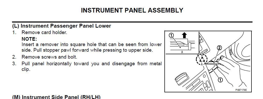
SECTION 3 – continued…) PASSENGER SIDE LOWER DASH REMOVAL
To remove the Passenger Side Lower Dash Panel, you first need to remove a few more bits of trim!
We need these panels off so we can run the cables from the Reversing Camera to the HU AND to allow us to find a suitable ‘space’ in which we will HIDE most of the radio HARNESS & LOOM; it’s *very tight* on space behind where the Head Unit will be installed (as a wise man once said “it’s tighter than a gnats chuff back there!â€)
– this is no JOKE…. it really is… if you have the NAV SCREEN as well, then you have even LESS ROOM ! A small compromise can be made if you are prepared to lose your “business card drawerâ€. Confused? All will become clear very soon!On the passenger side – pop off (lift and unclip) the kicking plate finisher INNER (in these pictures, the trim is already removed!) but will give you an idea; NSM# EI-35


Once that is removed, we need to remove the PASSENGER SIDE - DASH SIDE FINISHER – NSM#IP-10
The photo below shows the DASH SIDE FINISHER (on the opposite side of the car), I forgot to take a picture of the passenger side – but the important part here – is to dis-engage the two clips; so your panel looks like this ! * DON’T TRY AND REMOVE IT YET *

Next – you need to unscrew the plastic nut as shown in the pics. Below – then you can safely remove the DASH SIDE FINISHER PANEL.


To save losing the plastic NUT – I just screwed it back on!

..and NOW – the DASH PANEL itself!
Job #1 is to remove the “Business Card Drawerâ€; Seriously Nissan? This has to be the most ‘Peter Pointless’ thing on the Z…..
As you’ll read later - this “business card drawer†was a ‘bone of contention’ for me in this install…. especially when trying to ‘HIDE’ all of the cabling schmutz ! When faced with the decision about which was more important - ‘NEW Head Unit Cooling / Air Flow / Easy Install’ …or keeping the “drawer†and trying to squeeze a GAZILLION cables behind the HU – it was an easy choice! The Drawer had to go!

OK – back to Job#1 – Pull the drawer out until it stops; Using a LONG FLAT BLADE screwdriver – insert the slotted end of the screwdriver into the ‘GAP’ in the back of the drawer, rotate the driver while pulling the drawer forward;
There is a small TANG at the back which needs to be lifted up, to allow the drawer to be released. See pic;

Once the drawer is removed – remove the screw bolt – as shown in the next pic.

Now remove the screw as shown in the next pic.

NOTE : In some guides – it mentions there may be additional screws underneath (that hold the dash panel); these were not on my car…. I’d also seen pictures of a large METAL plate behind the dash panel (the NSM calls it a Knee Protector), but this was not on my car either! So – either they don’t exist on the MY06 – or somebody else (previous owner) had them taken off – and never put them back.
Slowly prise away the dash panel – unclipping from RIGHT to LEFT (see pic)

.. and lower it into the foot well.

Disconnect the CIGGY LIGHTER (12V ACC SOCKET) from the connector;

Put the panels somewhere safe for now!
CONGRATULATIONS – the LOWER DASH PANEL is removed.
NEXT STEP SECTION 4) HEAD UNIT PREPARATION & INSTALL
-
SECTION 3) INSTALLING THE BLUETOOTH MIC (INTO THE A-PILLAR) & PASSENGER SIDE LOWER DASH REMOVAL
First job of this section is to pull the door rubber (WELT) away from the body sufficiently to make room to unclip the first METAL CLIP which holds the A-PILLAR cover in-place; (See picture below)

Working from TOP to BOTTOM – make your way down the A-PILLAR unclipping as you go (using your fingers); take care not to interfere with the SIDE CURTAIN AIRBAG which can be clearly be seen in the picture below;

When you have finished unclipping downwards – the A-PILLAR cover should feel quite loose, but it is still secured at dashboard level; you need to gently and firmly pull towards yourself and slightly upwards which should release the A-PILLAR cover from the vehicle;
When it is removed – you’ll see a nice big hole – through which you’ll momentarily be “pulling†the AUDIO JACK end of the Bluetooth Mic;

Using a stiff piece of sheathed wire with the wire END taped-up (I used one of the cores from a length of COOKER cable); and working from the passenger seat, push the “cable puller†wire from LEFT to RIGHT (through the CABLE CONDUIT / HORIZONTAL CABLE CHANNEL) which is in the centre of the “CENTRE CONSOLE†– as shown in the picture below [...but the CONSOLE will not be there ! You have already removed it]; You are AIMING to “poke out†in the corner of the A-PILLAR; it takes patience, but once you can see the end of your “cable puller†– you’ll be ready to “pull the BlueTooth MIC†jack and cable back through – essentially "PULLING" it back behind the steering wheel side of the dashboard – and into the centre console (area);

Once the “cable puller†wire is poked through into the ‘corner’ – carefully and securely TAPE the MIC JACK to the “cable puller†end – I used DUCK TAPE for this; strong and versatile tape; and then VERY VERY GENTLY start to “pull†the MIC cable back through the CONDUIT until you reach the centre console; once it arrives – take up the bulk of the slack wire by pulling MOST of it through;
You can now SECURE your BlueTooth Microphone to the top of the A-PILLAR panel – and clip both the PANEL and the door rubber (WELT) back into place; Your MICROPHONE has now been mounted in the A-PILLAR; and the cable is ready to in the centre console (AREA) ready to plugin to the new Head Unit;

Sit back and ADMIRE your Handiwork !

NEXT STEP… SECTION 3 continued...) PASSENGER SIDE LOWER DASH REMOVAL
-
 1
1
-
-
SECTION 2) CENTRE CONSOLE / BOSE HEAD UNIT REMOVAL
The LINK shown below is a pretty good starting point for removing the centre console (however – it is written for a Left Hand Drive vehicle.. and does not show the NAV CONTROLS REMOVAL); so it can be a bit confusing;
http://liljerk.morpheus.net/350Z/dash_removal/
Have a read through the steps (BUT do not remove anything)– and then follow the steps from this point forward;
Start with the “shifter ring†– grab the front and gently lift upwards; now slide the whole thing down and rotate the assembly to the side; disconnect the flat white cable (from the heating / cooling controls) from the rear of the assembly – and the HAZARD SWITCH connector from underneath the assembly.

You can move this out of the way (as needed);
Removing the NAV CONTROL PANEL.
Insert a small jeweller’s screwdriver (flat blade) between the two pieces of trim – as shown below;

Using a second small jeweller’s screwdriver (flat blade)- make your way across prising the panel upwards;

Keep doing this across both sides until the top panel cover is free;

Pop the panel out – to reveal two screws underneath;

Remove the 2 x screws and place them somewhere safe; now lift the “NAV CONTROLS / BUTTONS†gently upward to expose the connector underneath;

Rotate the NAV controls to the side as shown below;

Press in the TANG / TAB on the WHITE CONNECTOR – and disconnect the NAV CONTROLS from the car; put the NAV CONTROLS somewhere safe (along with the 2 screws you removed a moment ago!).
Now you can see 2 more screws (these are shown with a RED CIRCLE) around them; these screws hold the TOP of the BOSE Stereo Mounting Brackets – so remove those, and place them somewhere safe;

The next step is to remove the SIX screws (as shown in the pictures below);


You are NOT removing the “WHITE BOX†– just undoing the screws to give you room to remove the existing Head Unit;
TAKE CARE not to damage or tear the WHITE FLAT CABLE while you are removing the screws;
GRASP the top of the Console (by the 3 x dials) with your fingertips – and GENTLY but FIRMLY pull towards you (TAKE CARE NOT TO PULL TOO HARD – YOU NEED TO CREATE JUST ENOUGH ROOM TO EXPOSE THE CONNECTOR AT THE BACK, SO YOU CAN DISCONNECT IT).
Now, carefully press in the TANG / TAB and remove the connector from the controls;
The CENTRE CONSOLE should now be quite loose, and manoeuvrable; with some expert ‘wiggling’ and some rotation (rotate slightly towards yourself); you should be able to tilt the console sufficiently to expose the rear of the BOSE HEAD UNIT;

From here – you can disconnect the ANTENNA (AERIAL) / plus the THREE CONNECTORS that plug-in to the back of the BOSE UNIT;
The ANTENNA just pulls outward; the other THREE WHITE connectors have TANGS / TABS that need to be pressed-in while you are gently but firmly removing them from the back of the HU;
Once all cables are disconnected – you can remove the whole centre console (with BOSE UNIT still attached / mounted); and take it somewhere flat and stable to work on the next steps; we will not remove the BOSE unit from the Console until STAGE 4;
Congratulations - the Centre Console is removed - Getting there slowly ! Don't give up !!!

NEXT………. we will now work on SECTION 3) INSTALLING THE BLUETOOTH MIC (INTO THE A-PILLAR) & PASSENGER SIDE LOWER DASH REMOVAL
-
I know there are ‘tons’ of guides on how to fit an aftermarket HU into a 350z, but there are some differences between MY’s (..and different OEM options like BirdView etc.);
So, here is my SUPERGUIDE for MY06 (FACELIFT) vehicles; on how to install a reversing camera and aftermarket Kenwood D-DIN HU (in my case, the Kenwood DDX-4028BT) to replace the Nissan OEM BOSE system (with tape deck); …but all original speakers / Bose AMP etc. are being retained. If you are swapping your HU anyway, then you may also want to fit a Reversing Camera at the same time (while the car is in bits!); Simplez !
In my configuration – I have the factory fitted Nissan BirdView system (which will be retained);
NOTE: By replacing the BOSE HU, you will ‘lose’ the NAVIGATION VOICE through the speakers; some members of the forum have solved this by either attaching a mini-speaker – or by wiring the NAV VOICE to a pair of RCA connectors (..and plug them into AUX); Personally, I decided NOT to bother; as the NAV VOICE is rather ‘annoying’ anyway !
You SHOULD be able to adapt this information to other ‘Kenwood’ HU models, it should be a similar install – however, you may need a different Head Unit Steering Wheel Controls adapter (e.g. the 29-005D instead of the 29-005).
The GUIDE will be posted in SECTIONS:-
SECTION 1) PREPARATION
SECTION 2) CENTRE CONSOLE / BOSE HEAD UNIT REMOVAL
SECTION 3) INSTALLING THE BLUETOOTH MIC (INTO THE A-PILLAR) & PASSENGER SIDE LOWER DASH REMOVAL
SECTION 4) HEAD UNIT PREPARATION & INSTALL
SECTION 5) INSTALLING THE REVERSING CAMERA
SECTION 6) FINAL RE-ASSEMBLY AND CONFIGURATION
NOTE: THIS GUIDE IS PROVIDED FOR INFORMATION PURPOSES; I CANNOT BE HELD RESPONSIBLE FOR ANY DAMAGE CAUSED AS A RESULT OF FOLLOWING THIS GUIDE. REMEMBER TO DISCONNECT THE BATTERY BEFORE COMMENCING ANY ELECTRICAL WORK, AND FOLLOW SAFE WORKING PRACTICES;
REMEMBER TO EJECT ANY CD’S/ TAPES FROM YOUR ORIGINAL UNIT BEFORE REMOVAL!!!!!
IF you intend to re-fit the BOSE original Audio System in the future, you should also perform the DAMPER LOCK procedure (as described in the Service Manual).
Locking CD Auto Changer Mechanism (Audio unit of BOSE system)
CAUTION:
Prior to removing a malfunctioning CD auto changer unit (Audio unit of BOSE system) that will be shipped for repair, the changer mechanism MUST BE LOCKED to prevent the mechanism from being damaged during shipping.
If a CD is jammed or unable to be removed from the unit, do NOT lock the changer mechanism. If the unit is to be shipped for repair, carefully package the unit to prevent vibration and shock.
DAMPER LOCK PROCEDURE
1. Eject and remove any CDs from the audio unit (BOSE system).
2. Turn ignition switch OFF. Wait until audio unit (BOSE system) display is off and mechanism stops moving (mechanism sound stops).
3. Press any one of the disc selection buttons once. When a display shows on the audio unit (BOSE system), press the same disc selection button again within 5 seconds. _ The changer mechanism will lock itself within 10 seconds.
4. After mechanism stops moving (mechanism sound stops), open the driver and passenger window, and then disconnect negative battery cable.
BATTERY DISCONNECT / AUTO WINDOW CLOSURES CAUTION:
After the battery cables are disconnected, do not open/close the driver and/or front passenger door with the window in the full up position. The automatic window adjusting function will not work and the side roof panel may be damaged.
NOTE:
After installing a new or remanufactured audio unit (BOSE system), switching the audio unit (BOSE system) ON will automatically unlock the mechanism.
NOTE: A special unlocking procedure is not required.
YOU WILL REQUIRE:-
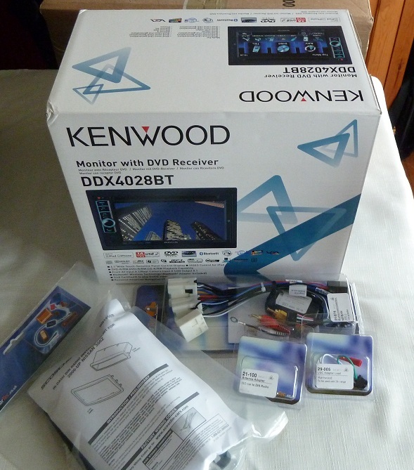
1 X KENWOOD DDX-4028BT HEAD UNIT
(PLUS the items as shown below from SEXTONS)
1 X REVERSING CAMERA (NUMBER PLATE BULB HOLDER STYLE)
Mine was from flea-bay – Sony ¼†CCD (520 TVL) – about £22 shipped from Hong Kong;
(It did take 10 days to arrive, so if you want one – order in advance!)
TOOLS
Include : 20-25W soldering iron, solder, crimps, crimping tool, heat shrink tubing, spare wire, etc. etc.
[EDIT] You may also want to consider "TRIM REMOVAL TOOLS" *Thanks to glrnet for this TIP* instead of using jewellers screwdrivers to take off the plastic dash trim (such as around the SAT NAV CONTROLS)
Links here :-
http://www.dal-tec.com/engineers-suppli ... c-177.html
http://www.screwfix.com/p/trim-removal- ... &source=aw
HAVE PLENTY OF PATIENCE!!!!!! TAKE YOUR TIME….. Some parts of the install are a really big P.I.T.A….. If something is not going well, just leave it alone for a while – and come back to it later. You’ll thank me later for this tip !
There are lots of great GUIDES on what bits you need to buy, for example (this thread)
I spent quite a few weeks reading all of the different forum threads and posts on I.C.E installs – including some really old ones; SOME questions went unanswered, so I felt about 90% prepared going into this install; that said, I used that knowledge to install my equipment (generally without too many problems); Seriously, take your time – and all should go OK.
If you are READY TO BEGIN – then let’s go:-
SECTION 1) PREPARATION
Specifically, I purchased the following bits:-
Parts List (SEXTONS DIRECT)
29-674 NISSAN 350Z (BOSE) USC LOOM
29-005 STEERING CONTROLS HEADUNIT SPECIFIC ADAPTER (KENWOOD) *single wire*
{This is the correct PART for the DDX-4028BT}
{NOTE : Some Kenwood HU’s have a 4 pin socket [not single wire]}
{Check your Kenwood HU Installers guide to see which type you need}
{If you have the 4 pin type – you will need the 29-005D}
50-306 FASCIA KIT – DOUBLE-DIN (OR SINGLE DIN + POCKET)
PARTS DETAILS
50-306 DOUBLE-DIN FASCIA KIT (MY2006 > ONWARDS)
SEXTONS DIRECT - http://www.sextonsdirect.co.uk/ict/p~50-306.html?cat=0
MANUAL FOR 50-306 - http://www.scosche.com/ecom/download/NN1456B.pdf
29-674 NISSAN 350Z (BOSE) USC LOOM
InCarTec Universal Steering Wheel Control Loom with Car Specific connectors to ISO.
SEXTONS DIRECT - http://www.sextonsdirect.co.uk/ict/p~29-674.html?cat=0
29-005 STEERING CONTROLS HEADUNIT SPECIFIC ADAPTER (KENWOOD) *single wire*
Head Unit specific – SWC adapter
SEXTONS DIRECT - http://www.sextonsdirect.co.uk/ict/p~29-005.html?cat=0
THE PICTURE ON THE SEXTONS WEBSITE IS *INCORRECT* FOR THIS ADAPTER (IT SHOWS AN MINI-AUDIO JACK ON THE END) – THIS PARTICULAR HEAD UNIT USES A SINGLE WIRE (NO JACK).
It looks like the picture below……………. (The little plug on the right with two wires that connects to the STALK ADAPTER)
Assemble the 29-674 ICT LOOM
• The ICT Loom requires very little in way of preparation, however:
o You will need to connect the “Stalk Adapter†(The box of tricks included in the kit) to the ICT Loom. According to the label, my “Stalk Adapter†was running V.2.14 of the SWC code.
All steering wheel control buttons work (except for the TELEPHONE one!) The “TALK / ANSWER†button changes the SOURCE; Volume Up/Down – Track Up /Down (..or Radio tune etc.)
o You will ALSO need to connect the “Head Unit Specific†cable (e.g. 29-005) also to the “Stalk Adapterâ€
This can be seen here…

Connect the ICT Loom to the Kenwood ISO Harness (provided with your Kenwood HU)
• Once again, this is quite straightforward
o Connect the 8 pin FEMALE connector (FROM the ICT LOOM) – to the ‘A’ BLOCK of the Kenwood ISO Harness (sometimes called Connector ‘A’ in the Kenwood install guide)
o The ‘A’ block has FIVE wires connected to the 8 pin MALE side including Black, Yellow, Red, Orange, and Blue (White Stripe).
o See image below (red circle)

• Essentially what you are doing here is passing the power, ACC (ignition live) and earth [amongst other things] through the ICT Loom to the ISO harness. The colours should match either side of the connector (use the YELLOW wire as the best guide)
• On the newer ICT Looms (from InCarTec / Sextons) – the 29-674 now comes with an additional wire (also BLACK) which is your pre-prepared EARTH - It is easily identifiable as it is a BLACK WIRE and has a crimped EYELET.
Previous guides on this forum suggested you needed to splice the EARTHS together and attach your own EYELET. This was not necessary in my case (Feb 2012), although making the EARTH wire a little bit longer makes install easier. If you plan to extend the EARTH – I would suggest cutting off the EYELET, and replacing it with an insulated SPADE / BLADE [MALE] connector; then make up a new length of wire (about 1 foot long) which has an EYELET on one end, and the SPADE SOCKET [FEMALE]; this makes connecting the EARTH wires easier – as you can attach them in advance to a suitable EARTH POINT (such as the SCREW BOLT near the GEAR lever!). For more info on why this is a good idea, see the section below on “Parking Brake Bypassâ€.

Complete the HARNESS
There are TWO extra wires which need to be connected for the harness to work correctly;
• On the ISO Harness – there are three cables with (TAGS) on them
o Cable 1 (BROWN) – Labelled “MUTE†– WE WILL NOT USE THIS
o Cable 2 – (LIGHT BLUE / Yellow Stripe) - Labelled “REMOTE CONT / STEERING CONTROLS†- this is for Steering Wheel Controls.

o Cable 3 (BLUE / WHITE Stripe) – Labelled “P.CONT / ANT.CONT†– this is the Remote Amplifier Power-ON cable.

JOB 1 – Prepare and join Cable 2
o Unfold the “REMOTE CONT / STEERING CONTROLS†wire – and strip the wire end
o TIN the wire-end using your soldering iron

o Using your crimping tool – attach a RED BULLET crimp connector and test it is secure.

o Connect the RED BULLET to the RED BULLET SOCKET on the “29-005 – Kenwood Stalk Adapter†cable and test it is secure.

o Wrap with INSULATING TAPE
JOB 2 – Prepare and join Cable 3
o Unfold the “P.CONT / ANT.CONT†wire – and strip the wire end to approx. 1cm / 12mm roughly.
o TIN the wire-end using your soldering iron
o You “COULD†use the CRIMPING METHOD here, but I found the CRIMP to be unreliable (later in the install), so I used a hook joint / solder method. *GRIN*
o Using a pair of small rounded pliers – curl the wire end to make a small HOOK *this is known as a solder hook joint.
I found some great soldering tips (including how to make Hook Joints) on this KIT CAR building website:-
http://www.r1ot.com/elecsys.htm
If you are a bit of solder novice, it’s definitely worth a look at the website.. KUDOS to Richard for a great website; and he knows his stuff – being an electrical engineer for the Royal Navy, and kit car builder.
o On the ICT Loom end, this already has a pre-attached RED BULLET crimp; (The cable is labelled “Amplifier Remote Turn onâ€). I cut this OFF, stripped 1cm and tinned the wire. Again using a pair of small rounded pliers – curl the wire end to make a small HOOK
o Now cut a NEW piece of wire about 4†long (I used 24 gauge) – strip 1cm off both ends, and tin.

o Using the a pair of small rounded pliers – curl the wire ends to make small HOOKs
o If you have it, slide 2 x pieces of “Heat Shrink Tubing†over the wires – and move to the middle (for now).
o Connect the two looms (by inserting the hooks together) and using your soldering iron – add additional SOLDER to the HOOK JOINTS. Make sure your joints are well soldered – but clean.
o Using a MULTIMETER (in Continuity mode) – probe the Blue / White WIRE (at one end of the ICT LOOM) – and the other end of the ISO LOOM (at the ISO connector end) blue/white wire (to check for a GOOD / SOUND connection); If all is good – then cover the two “hook joints†with your HEAT SHRINK TUBE – and seal the connections.
PROBLEM DIAGNOSIS : If you get “NO SOUND†from the HU, it is likely to be this cable that is badly joined. If you use the Hook Joint method (and NOT CRIMPING)– it should form a nice STRONG BOND especially once you have covered with the “Heat Shrink Tubingâ€. CRIMPING does work OK, but I personally found the ‘solder’ method more reliable.

The FINISHED HARNESS
If you look at the picture below – the “P.CONT†wire shown is ‘CRIMPED’; …but this FAILED later on in my install, so I reverted to ‘solder / hook joint’ method – as shown in the picture (ABOVE)

OPTIONAL STEP (Parking Brake BYPASS)
If you want to BYPASS the Parking Brake (NOT RECOMMENDED); you will need to accommodate for this now;
In the box for the Kenwood HU – there is a long LIGHT GREEN wire (For Safety REASONS - this cable is usually connected to the vehicle’s handbrake detection switch);
There is a short length of corresponding LIGHT GREEN wire (at the back of HU unit itself);
If you intend to BYPASS *cough* the parking brake – then you will need to SPLICE a length of this green wire either into the GROUND / EARTH (the black wire from the ICT Loom with the EYELET); …or just run a length of cable (approx. the same length as the BLACK pre-earthed cable from the ICT Loom OR a bit longer if you want an easier install) – and crimp a new eyelet onto it.
For GUIDANCE purposes, I used the “front / top left†screw from by the GEAR LEVER. Just remove the screw bolt – put the two earths (eyelets) under the screw – and re-attach tightly. This should give you a nice EARTH / GROUND point.
The two wires being sent to ground are:-
• Black Earth WIRE from the ICT Loom
• New Green WIRE from the rear of the Kenwood HU (Parking Brake)
See image below:
Well done for getting this far
…and now to SECTION 2) CENTRE CONSOLE / BOSE HEAD UNIT REMOVAL -
Any progress to report???
Hi mate
Yes; HU is in, Rear Camera is in and working.... just putting the final pieces of the car back together. It would have been finished today - but ran out of daylight.
Got loads of pics etc. for the write-up; quite a few places in the install that were are massive P.I.T.A$$ !
..but have carried on with it...
I'll get it written up before the end of the week ! Have you started yet, or are you waiting for my guide? PM back if you want.
Cheers
Mark
-
Welcome to the forum.. another Midlands based owner ?
Check out the regional area info... when you get 5 !
-
Also done - good luck chap !

-
How about something for breakfast?

This is a “special†from Jesters Café in Great Yarmouth.
Still feeling “hungry†?
-
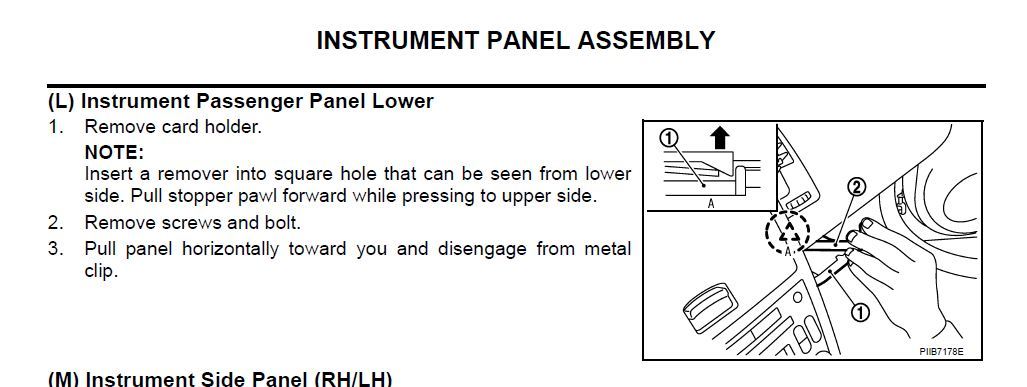
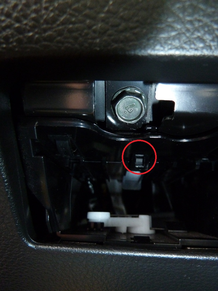
I've just removed my 'business card holder' (WTF Nissan, seriously?)
from the passenger side (above the 12V socket), and the removal process is similar (I think)There is a slot at the back of the 'holder' with a TAB on it; see red circle on photo (you can see the TAB you need to lift)
What you need to do is put a long flat blade screwdriver into the slot and turn it (to lift the TAB); with your other hand - you should be able to remove the cup holder / card holder.

-
Thanks Ian !
I've just grabbed another set of the SM's from *another forum* - and look what I found under IP.PDF
The "Instrument Panel" section [iP manual] is 2006 350z - Revision : 2005 August? Crazy... or what? I have six versions now... most of them very similar.. and this was the only one to feature the elusive "card holder"......

Still no mention of the ACC socket.......... though....
I'll do a bit more work on Weds and will be posting pics as part of my ICE install thread....
Cheers... if anybody else wants to 'chime in' - feel free.........
-
1) Yes & no need to disconnect battery
2) couple of screws & you need to remove the cup holder (flat blade screw driver to pop it out) before it comes out - I think theres another screw behind the cup holder
3) couple of screws & a bit of force
Ian - Thanks for the reply.
Regarding number 2) - The 2006 Model has a "Business Card Holder / Coin Tray" where earlier Z's would have a cup holder.... so not quite the same. The service manuals I have (for 2006 MY, 2006.5 and 2007 all have no mention of the "Card Holder", but I have seen an extract from a service manual which shows it.... now I can't find it. There is also a cigar lighter / 12V ACC socket directly beneath that which I assume also has to be removed / disconnected?
Regarding number 3) Does the bonnet release mechanism have to be removed from the panel first before the thing will come away?
Be very very careful in the cold weather as the trim will be liable to break more easily...
if you HAVE to remove trim in very cold weather run thr car with the heaters on full blast for a bit
Nice TIP Dave
 - problem is........... I have my heater controls disconnected at the moment (centre console is still out!), so have no control whatsover over the temperature in the car... I could re-connect as a temp measure.... but it's getting a bit stupid - having to re-connect bits to perform another task (like removing trim!)...... it's a bit like the "Magic Windows" trick when you are disconnecting the battery NEGATIVE....... roll-down windows, remove NEG, close door.... re-connect NEG, shut door, rolldown window, rollup window - dance..............................
 -
Evening all ! Not really an I.C.E thread...... but......
I'm fitting a new HU (Kenwood) and a couple of things are perplexing me..with the dash interior lower panel / a pillar trim removal - hopefully you guys can help !
No flaming please !
YES, I used the search button...... a lot ! ..and I've read and re-read the Service Manuals.2006 MY model - OEM Birdview Satnav (I already have the centre console removed, and modified waiting to go back in);
1) Is it safe to remove the drivers side door rubber *(welt) and A-Pillar cover to run a mic for the bluetooth to the HU?
- Is it OK to do this with the battery still connected, or would it be safer to do it with the battery off? I noticed the driver side curtain airbag disappearing off into the roof liner.... and didn't want to chance anything !
2) What is the removal process for the passenger side lower dash panel? Mine has the coin drawer / cigar lighter....... in the panel. I had a quick look underneath - and the dash was flapping around (I think there should be 2 x screws / bolts fixing that panel?) ..they were missing.... Any other bolts / screws or clips to remove - or can I just pull it towards myself horizontally as per the SM.
*hoping to hide all of the ICT Loom / ISO loom back there !* hence the questions.
3) Same question for the drivers side (lower dash panel)- but for the bonnet pull, fuel flap release, and switch bank for headlamp washers etc. *remove panel to cable bash the bluetooth mic lead*
Links are good (with photos even better).
Cheers in advance.
Mark
-
Awesome !
You've been doing the centre console 'hokey cokey' again then?
DAB rocks !
-
The steering wheel adapter is sorted now although I think my actual steering control unit needs updating, it has frozen a couple of times when I have been adjusting the volume from the steering wheel mine is version 1.9 and when I emailed ICT they said that I needed the newer version
Dave,
My “Stalk Adapter†is running V.2.14 - not fitted yet, but arrived this week (ICT 29-674)
Mark
-
Nice one !

Hope their e-Bay shop is more reliable ?
-
Awesome. As discussed you're doing exactly what I want to do so i'll be viewing with interest how this goes!
After a week with just the CD changer in the car im already ready to buy!!
Working on it ! I just PM'd you the supplier details !
Mark
-
Hi Dom
Not had dealings with these guys personally (they seem large enough with a few stores);
According to their Ts+Cs - they can only charge you (if you are happy to wait for the product to come into stock!); if not - they are legally obligated to cancel the order; they should not be charging you, IF out of stock - unless you already agreed to wait?
Availability
If for any reason beyond our reasonable control, we are unable to supply a particular item, we will notify you as soon as possible. Payment will be taken for out of stock products to secure stock, only if you are happy to proceed with the order and agree to wait for the product.
Which HU were you looking to get? I just purchased my Kenwood DDX4028BT (which is listed at £309.99 on Car Audio Centre), but I only paid £254.99 from a more reliable ICE supplier.
Hope you can get this sorted out quickly, and order your goods from elsewhere.
Mark
-
HUZZAH ! My goodies have started to arrive..............
...but Santa has been officially placed on my naughty list.
I've started working on my Kenwood ICE install guide (with rear cam) on MY06 with OEM SatNav.. hope the weather clears up so I can get busy over the weekend !
BTW - If anyone is in the market for a new HU - I had a bargain with my Kenwood DDX-4028BT...... only £254.99 + £9.99 next day courier. Purchased from a Kenwood Premier Centre. They seem pretty 'keen' on price, and was the cheapest I found (even cheaper than flea-bay!)
PM me if you want to know more details.
Install guide with plenty of pics / notes will be coming soon !
Ciao !


Trickle Charger
in 350Z General
Posted
Personally I have the CTEK Multi XS 7000 which is an awesome bit of kit; charges everything I've thrown at it (including the battery on the 350z) and it does trickle charge; it works with most battery chemistry too [including Spiral Cell / AGM and GEL]. A mechanic told me about the CTEK stuff.
It's a fair chunk of change - but its worth it. I've used it to charge batteries that were almost 'dead' where other chargers wouldn't even touch it. It comes with croc clips and eyelets for leaving on the battery, but you can buy other add-ons - eg. leads with small battery level meters;
Quick search - and I have an earlier version of this one:-
http://www.theultimatefinish.co.uk/ctek/multi-mxs-7-0-12v-battery-charger-and-conditioner.aspx
Worth a look at the CTEK website - as they have lots of new models too. http://www.ctek.com/gb/en
Best price I've seen the new one is around £100;